Note : Les descriptions sont présentées dans la langue officielle dans laquelle elles ont été soumises.
1 3 1 53 1 9
K 9451
FLOWLINE CONNECTOR
The invention relates to a flowline connector. More particularly
it relates to a flowline connector comprising a pin member which
can be snapped into a box member.
The connection of flowlines at difficult accessible locations,
such as in deep water near the sea bed, requires that the connection
between the flowlines can be made and released in a quick and
reliable manner.
Numerous flowline connector syste=s are known which are
intended to provide quick connection and release of the connector
parts. U.S. patent No. 3,419,071 discloses a multibore pipe connector
including remotely actuated hydraulic means for moving locking
fingers radially inward to lock flanges of ad~acent pipe sections
to each other. ~
U.S. patent No. 4,2S5,470 discloses a pin and~box type connector
15~ of which the connector parts~are loclced to each other by~æpring
loaded~locking~f~ingers which~are retained in a contracted position
by~a locking nut and sleeve assembIy surrounding the ~ingers.
U.S. patent No. 3,987,72g~ discloses~a flowline connec~tor of
; which the connector parts are~locked'to each;o~her~by a~split;
20~ , locking~ring instead of~loceing~fingers~so~as~to;avold the~;~high~
~anufacturine cost oE the~f~ngero~ In the~connector deslgn~kn~n
fro~thi6 patent the split~locking~ring is~forced~into its locking
~position~by,moving~a;tapered~cleeve in~axial directlon~over the~
ring,~whereàs~the locking ring is~permitted to~ expand to lts~
~:: 25 i~ ~ ~unlocked position by~oving~tha s~leeve~in an,~opposite direetion. To
assist the locking~ring to expand to~its uNloc~ed'position~the
sleeve ls provided~with a~conical~member~which is~arranged in the
open spac~e left between the ad~acent ends of the spl~it l'ocking
ring~, which~member forces said~ends away from each~other when the
sleeve is moved in said opposite direction. ~ a~sadvantage of this
:
1 3 1 53 1 9
-- 2 --
known configuration is the complex assembly of a sleeve and conical
member to move the split locking ring be~ween its expanded and
retracted position.
Accordingly it is an object of the invention to provide a snap
type flowline connector provided with a split locking ring which
can be moved between a contracted and expanded position by less
complicated actuator means.
It is a further object to provide a snap type flowllne connector
of which the locking ring can be quickly moved from its expanded
locked position into its compressed unlocked position even if a
tension force is present between the adJacent connector members.
The flowline connector according to the invention thereto
comprises
- a pin member and a box member, said pin member fitting co-
axially within said box member,
- a split locking ring which is arranged in a locking ring
retaining groove at the external surface of the pin member,
said locklng ring being sized to fit in a normally assumed
expanded position thereof in a locking ring receptor groove at
the internal surface of the bo~;member,
- a compression;sleeve ~hich at ~ea6t partly surrounds said
locking ring, said compression~sleeve being axially slidable
relative to the pin member between a first position in which
there;iæ~a sma11 ov6rl6p between the s1eeve~and ring,~and~6
~ second~position in which there is~a~larg~er~overlap between the~
sleeve and~ring, and
- actuator means for~inducing~said compression sleeve~to slide~
between~said first~and~second~posit~ion s~ as to~move said
locking ring from~an expanded to~a contracted position and
vice~versa.;
The key element in the flowline~connector according to the
invention is the compression sleeve,~which is moved over the split
lockin~ ring to move said~ring from its expanded locked~position to
its compressed unlocked position. The compresslon sleeve is able to
unlock the split locking ring even if a tension force is present
1 3 1 S3 1 q
between the connector members, so that always quick disconnection
of the members is possible.
The invention will now be explained in more detail with
reference to the accompanying drawings, in which:
Fig. lA is a sectional view of the upper part of the flowline
connector according to the invention in a locked position thereof;
; Fig. lB is a sectional view of the lower part of the flowline
connector according to the invention in an unlocked position
~hereof;
Fig. 2 is a cross-sectional view of the stab subs in the
connector of Figo lA and lB as seen along broken lines E-E;
; Fig. 3 shows the operation of a pull-in device that is used to
pull the pin member into the box member, and;
Fig. 4 is a sectional view of the pull-in device of Fig. 3
seen along hroken line IV-IV.
; In the accompanying drawings similar reference numerals
designate similar parts of ~he connector and associated equipment.
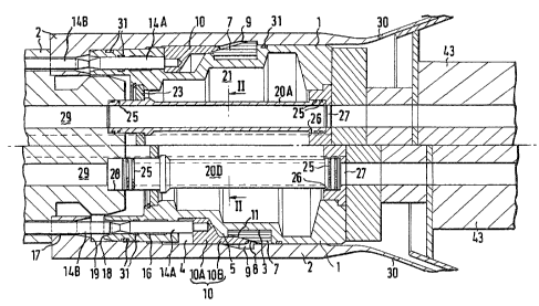
In Fig. lA and lB there is shown a snap type flowline connector
comprising a~pin member 1 which fits co-axially in~a box member 2.
The pin member~l~comprises~a tubular body~provided~at the~external
surface~thereof with a~10cking~riDg retain~ng~g~oove 3;and a
compression sleeve~groove~4,~which~grooves are sep~arated by an
annular shoulder 5. In the;locking~ling retaining groove;3~there:is
arranged~a split~locking~ring 7 having a~tapered o~ter~surface 8.
2S ~ ~ The~10cking rlng~7~ is sized to`fit~ in a~normally expanded~position ~,
thereof~(as illustrated in Fig. lAi~l~ in~a 10ckiDg~ring;~receptor~
roove~9 at~the;~-iDterDal sDrfac2~0f~the box;member 2~.~;A compression ~ ~ -
slee~ve~10 is~s~lidably arranged~in~the~compression sleeve~groove 4.
The;~compréssion~sleeve IO;~has~a cylinar1csl~outsr`sDrface and à~
~stepwise~ increasing internal~diameter~ such~that~th~sleeve ~s
composed of a~small diameter ~ection~10~fitting~in ths comp~ression
ring groove 4,~;and a large diameter~section IOB which slidably
surrounds the~annular shoulder 5. The large diameter sleeve
section~lOB~comprises an inwardly~flared~end portion 11 which at
least partly surrounds the tapered outer surface 8 of the~locking
ring.,
', '.
1 3 1 5~ 1 q
A plurallty of rod assemblies 14A, 14B are provlded for moving
the compression sleeve 10 between a first position (as illustrated
in Fig. lA) in which there is a small overlap between the sleeve 10
and ring 79 and a second position (as illustrated in Fig. lB) in
which there is a larger overlap between the sleeve 10 and ring 7.
Each rod assembly L4A~ 14B comprises a first rod 14A which is
screwed to the compression sleeve 10 and a second rod 14B which is
mounted on a hydraulically actuated piston (not shown) in the box
member 2. Each first rod 14A is slidably arranged in an axial
opening 16 in the pin member 1 and each second rod 14B is slidably
arranged in a corresponding axial opening 17 in the box member 2.
The openings 16 and 17 are axially aligned and pass through abutting
end faces 18 and 19 of the pin and box member. By actuating the
hydraulic pistons the rod assemblies 14A, 14B can be moved synchro-
neously from the contracted position shown in Fig. lA to the
extended position shown in Fig. lB thereby moving the compression
sleeve to move from its first~to its second position and urging the
split locking ring to be contracted;to its unlocked position.
The movement of the compression sleeve in opposite direction,
i.e. from its second to its~first position, i~s~initiated by the use
of Belle Ville spring washers (not shown)~, which~puIl the compression
:
sleeve 10 away from the lockingjring 7.
The;pin member 1 carries~four~s~tab~ sobs~20A-D~(see~also
Fig. 2). The stab~subs~20A-D are~arranged~in~a central~opening~21
within the p~n member l~and they are supported in a substantia~ly
ngitudinal~orientation~by a~perforated support disk Z3~whlch is
cross-axially arranged in said opening 21 at a location close~ to~
the end~face 18 o~f the~pin member 2. Each~stab~sub is~at one end
thereof sealingly f1tted in~an~enlarged end portio~n 26~of A~ f1~id
passageway 27 in the pin member. Each~;~stab sub is-at the~other end~
thereof sized to be sealingly stabbed into an enlarged end portion 28
of a corresponding fluid passageway 29 in the~box member 2. Sealing
between the outer surface of the stab subs 20A-D and the internal
surface of the enlarged end portions 26, 28 of the fluid passage-
ways 27, 29 ln the pin and box member is provided by a plurality of
.
1 31 531 9
flexible seal-rings 25. The arrangement of the stab subs 20A-D
ensures that a reliable and leakage free connection can be made
between the corresponding passageways in the pin and box member
even in case of a slight misalignment between the members.
As illustrated in Fig. lA and B the box member 2 comprises a
guide funnel 30 for guiding the pin member 1 in a co-axial positlon
relative to the box member 2 during the puli-in procedure. In order
to enable easy connection and release of the connector members the
box member 2 has an internal diameter which increases stepwise in a
direction from the end face 19 to the guide funnel 30. The pin
member has an external diameter which stepwise increases in a
corresponding manner in said direction.
In order to avoid the entrance of solid debis in the area of
the locking ring 7 and other moving parts a series of sealing
rings 31 are arranged at the external surface of the pin member and
within the axial openings 17 housing the rods 14A.
The connector operates as follows. When the pin member l is
pulled into the box member 2 the seeond rods 14B are in the extended
positlon (as illustrated in FiB. IB3~and push~the~compression
sleeve 10 in the~second po~sition'thereof. Hence~the 'locking ring `~
is~pushed in the contracted~position~thereof.~When~tbe~pin member l~
has~reached`the~position~shown~in~Fig. lA~the~compression~sleeve is
; moved ~owards~the~first~posit~ion the~eof~by;contracting~the;;~rod
assemblies 14A, 14B thereby enabling~the~locking;ring~7~to snap~
25 ~ lnto~the~loc~ing,~r1ng~receptor;~g~oove;9 st the internal~surface~of;
~;box~member.
If~disc~onnec~tion o~the~pin member~ f`rom the box member,2 is
required~the rod~assemblies 14A, 14B~are~actuated'by~means~of the
hydrau~lically~actuated pistons~ not shown~ to move~`the~compression~
30~ sleeve lO from~`the~first~po6ition (shown ~n~Fig.~lA),~o~the~second~
position the~reof~(shown i'n-Fig~lB?. Said movement of~the compression
sleeve 1:0 over the tapered surface 8 of the qp~lit Iocking ring 7'
forces the locking ring 7 to contract thereby~releasing~the~locking
r~ng 7 from the locking ring~receptor groove 9~at the internal
surface of the box member 2. Subsequently the axisl force exerted
- '
.
'-` 131531q
by the rods 14a to the compression sleeve 10 i8 transferred via the
annular shoulder S to the pin member 1 thereby pushing the pin
member 1 a~ay from the box member 2.
The assembly of rods 14A, B and compression æleeve 10 thus
provide a simple and reliable actuator mechanism which is able to
force the split locking ring into its contracted, unlocked, position
and to subsequeDt1y push the pin member 1 away from the box member 2.
As illustrated in Figs. 3 and 4 the box member 1 may be
arranged on a submerged or floating structure 35, and the pin
member 1 may be located at the end of a multibore flexible conduit 43.
In that situation the procedure of pulling the pin member 1 into
the box member 2 may be carried out by a remotely operated pull-in
devlce 36 which is landed on a pair of guide posts 37 which are
arranged on the structure 35 ad~acent to the box member 2.
The pull-in device comprises a pair of hooks 38,39 cooperating
with a pair of studs 40 mounted latidunally~on the pin member 1.
The hooks 38, 39 are mounted on a pair of substantially~parallel
hydraulic pisto~s 41, 42 which can be~retracted synchroneously in
order tD pull the~pin member l~in a substantia1~1y axially~aligned~
position into~the box member 2.
The guide~funnel 30 comprises an;~axial slit 46 cooperating~
with~a pulling~eye~4a mounted on~the~pin~member~ and~in the;~
prolong~ation~Df`thé s~de wa1Is of the~slit~46~a~pair~;of~guide
members 47 are-provided ~n order to~induce~the~pin member 1 to
slide~in a predetermin2d~0rientation~into-the box~member~2.
Fig. 4 shows~the~pull-in device;~36 àfter~it~has;been;~'emp~Ioyed
to pull the~pi~n member l~into the~bo~ member~ 2. At~the end of the
coupling~procédure the pull-in device 36~may be~retrieved from~the
~ ~guide posts~3~7;~after re1éase~Df~the~hDDks~38,~39~from~the~seuds 40.
30~ The~device~36'~may~be reinstalled on~the~guide~posts 37 if~discQn~
nection of the~connector members is required. During~the discon-~
nect~Dn procedure~the hooks~38', 39~may~pull~the pin member 1 intD
the box member 2 while the rod assemblies push the compression
~sleeve 10 over the split locking ring 7 so as to enable easy~
release of the 1Ocking ring 7"from the locking rlng~receptor ~ ~
:
.
1 3 1 53 1 9
-- 7 --
groove 9. A detailed description of the operation and procedures
for retrieval and reinstallation of the pull-in device shown in
Fig. 3 and 4 has besn disclosed in Applicant's British patent
application No. 8520704 (publication No. 2J163,404).
It will be understood that instead of using the pull-in device
shown in Fig. 3 and 4 other remotely operated pull-in devices may
be used as well.
It will further be understood that the flowline connector
according to the invention may be used to couple any type of single
bore or multibore flowlines at both offshore or onshore locations.
'
::
.
: