Sélection de la langue

Search

Sommaire du brevet 1319019 

Énoncé de désistement de responsabilité concernant l'information provenant de tiers

Une partie des informations de ce site Web a été fournie par des sources externes. Le gouvernement du Canada n'assume aucune responsabilité concernant la précision, l'actualité ou la fiabilité des informations fournies par les sources externes. Les utilisateurs qui désirent employer cette information devraient consulter directement la source des informations. Le contenu fourni par les sources externes n'est pas assujetti aux exigences sur les langues officielles, la protection des renseignements personnels et l'accessibilité.

Disponibilité de l'Abrégé et des Revendications

L'apparition de différences dans le texte et l'image des Revendications et de l'Abrégé dépend du moment auquel le document est publié. Les textes des Revendications et de l'Abrégé sont affichés :

  • lorsque la demande peut être examinée par le public;
  • lorsque le brevet est émis (délivrance).
(12) Brevet: (11) CA 1319019
(21) Numéro de la demande: 590679
(54) Titre français: SOULEVEUSE POUR MOISSONNEUSE-ANDAINEUSE OU MOISSONEUSE-BATTEUSE
(54) Titre anglais: CROP LIFTER FOR SWATHERS OR COMBINES
Statut: Périmé
Données bibliographiques
Abrégés

Abrégé anglais


CROP LITTER FOR SWATHERS OR COMBINES
ABSTRACT
Conventionally, such lifters are relatively
long and cause problems with control of the header and
proper lifting of the crops without shattering or shell-
ing occurring. The present lifter is relatively short
and is bolted to the header using one the bolts attaching
the knife guard to the header. The head is floating so
that the lifter rides just on the surface and just in
front of the guard so that it picks up the crop and lifts
them over the knife assembly and onto the header.

Revendications

Note : Les revendications sont présentées dans la langue officielle dans laquelle elles ont été soumises.


- 8 -

CLAIMS
1. A crop lifter for use with a combine or swather
which includes a transverse knife blade assembly on a header
and a plurality of spaced and parallel knife guards each with
a front end extending forwardly of the header, said crop
lifter including a downwardly extending ground engaging front
portion and a substantially horizontal header attachment
portion close coupled behind the front portion and means on
said lifter to engage the front end of an associated one of
the guards for rigidly stabilizing said lifter both
vertically and horizontally.
2. The lifter according to claim 1 in which said
means to engage the front end of the associated one of the
guards comprises an apertured gusset portion on an under side
of the lifter between the ground engaging portion and the
attaching portion, said gusset portion engaging the front end
of the associated one of the guards and being supported
thereby.
3. The lifter according to claim 1 which includes
an apertured plate extending rearwardly of said attaching
portion engageable upon an upper side of the header and
bolted thereto by fastening means attaching the associated
one of the guards to the header.
4. The lifter according to claim 2 which includes
an apertured plate extending rearwardly of said attaching
portion engageable upon an upper side of the header and


-9-

bolted thereto by fastening means attaching the associated
one of the guards to the header.
(5) The lifter according to claim 3 which includes
spacer means between said plate and said header to vary the
aggressiveness of said lifter relative to a ground surface
being traversed by the header and to adapt said lifter for
attachment to various types of swathers.
(6) The lifter according to claim 4 which includes
spacer means between said plate and said header to vary the
aggressiveness of said lifter relative to a ground surface
being traversed by the header and to adapt said lifter for
attachment to various types of swathers.
(7) The lifter according to claim 1 in which said
ground engaging portion angles downwardly from the header
attachment portion and includes a horizontal ground engaging
under surface.
(8) The lifter according to claim 2 in which said
ground engaging portion angles downwardly from the header
attachment portion and includes a horizontal ground engaging
under surface.
(9) The lifter according to claim 3 in which said
ground engaging portion angles downwardly from the header
attachment portion and includes a horizontal ground engaging
under surface,
(10) The lifter according to claim 4 in which said
ground engaging portion angles downwardly from the header


-10-
attachment portion and includes a horizontal ground engaging
under surface.
(11) The lifter according to claim 5 in which said
ground engaging portion angles downwardly from the header
attachment portion and includes a horizontal ground engaging
under surface.
(12) The lifter according to claim 6 in which said
ground engaging portion angles downwardly from the header
attachment portion and includes a horizontal ground engaging
under surface.


Description

Note : Les descriptions sont présentées dans la langue officielle dans laquelle elles ont été soumises.


1~19~9
- 1 -


CROP LI~TER FOR SWATHERS OR COMBINES
BACKGROUND OF THE INVENTION
This invention relates to new and useful improvements in
crop lifters, particularly lifters used on pulse type
crop vines such as peas, lentils and the like.
Conventional lifters extend forwardly a consi-
derable distance from the knife guards and although they
may be satisfactory to lift certain types of crops,
nevertheless when dealing with pulse crops, the tendency
of such crops to shatter and shell makes it difficult to
use such long lifters. Furthermore, with the header in a
floating position, such lifters tend to vibrate the crops
as they are lifted and the considerable diskance that
they have to be engaged by the lifters often results in
damage occurring to the crop prior to the cutting action
of the transverse knife assembly situated on the front
edge of the header. There is less danger of bending the
lifters of the present invention during turning.
The present device overcomes these disadvan-
tages by providing a relatively short and close coupled
crop lifter, the forward end of which is only relatively
short distance in front of the knife guards. It is used
primarily to lift pulse crops such as peas and lentils
off the ground for swathing or combining and the lifters


~3~
-- 2

are bolted on-to the header using one of the bolts which
attaches -the !cnife guards so -that the lifter projects
forwardly and downwardly -to the ground. The lifters can, of
course, be used on other types of crops.
The header may then be floa-ted so that the crop
lifter just rides on -the ground and picks up the crop to get
them over the knife assembly and onto the header with the
minimum disturbance occurring prior to the knife assembly
severing the plants.
By contrast, present devices, being relatively long,
cause problems of control of the header with proper lifting
of the crops and some such lif-ters catch on the crop,
particularly when backing out of a wet spot. Furthermore,
bending of conventional liftexs is a problem when turning.
In accordance with the invention there is provided a
crop lifter for use with a combine or swather which includes
a transverse knife blade assembly on a header and a plurality
of spaced and parallel knife guards each with a front end
extending forwardly of the header, said crop lifter including
a downwardly extending ground engaging front portion and a
substantially horizontal header attachment portion close
coupled behind the fron-t portion and means on said lifter to
engage the front end of an associated one of the guards for
rigidly stabilizing said lifter both vertically and
horizontally~


t~
.j~,.

~319~9


Another advantage of the invention is to pro-
vide crop lifters that may be spaced along the length of
the header for example, every 6" or 9" and may be left on
the header when used with other crops without interfering
with the action of the header.
A further advantage of the invention is to pro-
vide a device of the character herewithin described which
is simple in construction, economical in manufacture and
otherwise well suited to the purpose of which it is
designed.
With the foregoing in view, and other advan-
tages as will become apparent to those skilled in the art
to which this invention relates as this specification
proceeds, the invention is herein described by reference
to the accompanying drawings forming a part hereof, which
includes a description of the best mode known to the
applicant and of the preferred typical embodiment of the
principles of the present invention, in which:
DESCRIPTION OF THE DRAWINGS
_ _ _
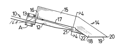
Figure 1 is a side elevation of the device
shown installed on a header.
Figure 2 is a view similar to Figure 1 but
showing the spacers used to control the aggressiveness of


J.~

1~9~


the crop liEter relative to the ground.
Figure 3 is a partially schematic top plan view of
Figure l;
Figure 4 is a section along the line 4-4 of Figure 1
but with the guard removed.
In the drawings like characters of reference indicate
corresponding parts in the diferent figures.

DETAILED DESCRI TION
Proceeding therefore to describe the invention in
detail, reference character 10 illustrates generally and
schematically, a conventional header used on combines or
swathers. It includes a transverse reciprocal knife shown
schematically by reference character 11 with the knife being
supported by conventional guards 12 which are bolted to the
header 10 by means of bolts 13 and extend forwardly therefrom
in spaced and parallel relation~hip.
The invention collectively designated 14 may be
secured across the width of the header at approxi~lately 6" or
9" intervals, by utilizing one of the bolts normally holding
the guards 12 to the header; such a bolt is shown by
reference character 13 as hereinbefore des-


`` 1 3 ~ 9


cribed.
The lndlvidual crop lifters consist of a headerattaching portion 15 which is basically horizontal and which
includes a flat plate 16 secured to the underside 17 of the
horizontal por-tion and ex-tendiny rearwardly therefrom. This
plate is slot aper-tured as at 16A and is engaged by the bolt
13 passing through -the header 10 and clamping the g~ard 12 in
position.
Extending downwardly and forwardly from the front end
of the horizontal por-tion 15 is a ground engaging front
portion 18 which angles downwardly and terminates in a planar
ground engaging forward nose portion 19.
It will be noted that the forward extremity 20 of
this portion is relatively close to -the front end 21 of the
guard 12 so that the crop is lifted over the knife assembly
and onto the header with the minimum disturbance and allows
very short stubble to remain after -the knife has severed the
crop.
The lifters are rigidly stabilized by a gusset
portion 22 secured to the under side of the lifter adjacen~
the junction of the horizontal portion 15 with the ground
engaging portion 18 and this portion faces rearwardly is
provided with a tapered blind aperture 22A which and en-


13~g~9


gages over the front end 21 of the guard thus stabilizingand supporting the lifter both vertically and horizontal-
ly once it is bolted to the header by means oE bolt 13.
The ag~ressiveness of the lifter may be ad-
justed within limits by the provision of spacers 23 situ-
ated below the flat plate 16 and above the header 10.
This tilts the lifter downwardly pivoting around the gus-
set portion 22 and the front end 21 of the guard.
It should be appreciated that it is highly de-
sirable to get the header as close to the ground as
possible in order to leave as little stubble as possible,
particularly when used for pulse crop vines and the like,
a condition which is not possible with conventional rela-
tively long lifters. These lifters also need to be rela-
tively short for lentils, peas and the like in order to
prevent shattering or shelling because conventional rela-
tively long lifters disturb the crop too far ahead o~ the
header thus permitting damage to the crop to occur.
Due to the relative shortness of the lifters
and unlike conventional lifters, the lifters o~ this
invention may be left on the ~achine when used for wheat
or the like and in fact they may, under certain
circumstances be useful for wheat crops and the like if
the crop is wet or lying on the ground thus eliminating


~319Q~9


the need for a conventional pick up reel.
It is easily adaptable for use on most makes of
combines or swathers and is readily attachable thereto.
It is also easily adapted Eor use with floating
cutter bars and may act as a spacer so that small rocks,
stones and the like pass underneath the cutter bar rather
than being picked up thereby and passed to the swather or
combine mechanism.
In some cases a pick-up reel may not be
re~uired when the lifters of this invention are installed
and furthermore, higher swathing speeds may be attained.
Since various modifications can be made in my
invention as hereinabove described, and many apparently
widely different embodiments of same made within the
spirit and scope of the claims without departing from
such spirit and scope, it is intended that all matter
contained in the accompanying specification shall be
interpreted as illustrative only and not in a limiting
sense.


Dessin représentatif
Une figure unique qui représente un dessin illustrant l'invention.
États administratifs

Pour une meilleure compréhension de l'état de la demande ou brevet qui figure sur cette page, la rubrique Mise en garde , et les descriptions de Brevet , États administratifs , Taxes périodiques et Historique des paiements devraient être consultées.

États administratifs

Titre Date
Date de délivrance prévu 1993-06-15
(22) Dépôt 1989-01-16
(45) Délivré 1993-06-15
Expiré 2010-06-15

Historique d'abandonnement

Il n'y a pas d'historique d'abandonnement

Historique des paiements

Type de taxes Anniversaire Échéance Montant payé Date payée
Le dépôt d'une demande de brevet 0,00 $ 1989-01-16
Enregistrement de documents 0,00 $ 1989-09-15
Taxe de maintien en état - brevet - ancienne loi 2 1995-06-15 50,00 $ 1995-05-31
Taxe de maintien en état - brevet - ancienne loi 3 1996-06-17 50,00 $ 1996-04-29
Taxe de maintien en état - brevet - ancienne loi 4 1997-06-16 50,00 $ 1997-06-13
Taxe de maintien en état - brevet - ancienne loi 5 1998-06-15 75,00 $ 1998-06-11
Taxe de maintien en état - brevet - ancienne loi 6 1999-06-15 75,00 $ 1999-05-10
Taxe de maintien en état - brevet - ancienne loi 7 2000-06-15 75,00 $ 2000-06-05
Taxe de maintien en état - brevet - ancienne loi 8 2001-06-15 75,00 $ 2001-03-29
Taxe de maintien en état - brevet - ancienne loi 9 2002-06-17 75,00 $ 2002-04-29
Taxe de maintien en état - brevet - ancienne loi 10 2003-06-16 100,00 $ 2003-06-02
Taxe de maintien en état - brevet - ancienne loi 11 2004-06-15 125,00 $ 2004-04-23
Taxe de maintien en état - brevet - ancienne loi 12 2005-06-15 125,00 $ 2005-05-11
Taxe de maintien en état - brevet - ancienne loi 13 2006-06-15 125,00 $ 2006-06-12
Taxe de maintien en état - brevet - ancienne loi 14 2007-06-15 125,00 $ 2007-04-20
Taxe de maintien en état - brevet - ancienne loi 15 2008-06-16 225,00 $ 2008-05-13
Taxe de maintien en état - brevet - ancienne loi 16 2009-06-15 425,00 $ 2009-07-13
Titulaires au dossier

Les titulaires actuels et antérieures au dossier sont affichés en ordre alphabétique.

Titulaires actuels au dossier
EAGLE AIR LTD.
Titulaires antérieures au dossier
MEDERNACH, LOUIS J.
Les propriétaires antérieurs qui ne figurent pas dans la liste des « Propriétaires au dossier » apparaîtront dans d'autres documents au dossier.
Documents

Pour visionner les fichiers sélectionnés, entrer le code reCAPTCHA :


Pour visualiser une image, cliquer sur un lien dans la colonne description du document. Pour télécharger l'image (les images), cliquer l'une ou plusieurs cases à cocher dans la première colonne et ensuite cliquer sur le bouton "Télécharger sélection en format PDF (archive Zip)" ou le bouton "Télécharger sélection (en un fichier PDF fusionné)".

Liste des documents de brevet publiés et non publiés sur la BDBC .

Si vous avez des difficultés à accéder au contenu, veuillez communiquer avec le Centre de services à la clientèle au 1-866-997-1936, ou envoyer un courriel au Centre de service à la clientèle de l'OPIC.


Description du
Document 
Date
(yyyy-mm-dd) 
Nombre de pages   Taille de l'image (Ko) 
Demande d'examen 1991-01-28 1 43
Demande d'examen 1991-11-28 1 64
Correspondance reliée au PCT 1993-03-25 2 33
Correspondance de la poursuite 1992-05-28 3 113
Correspondance de la poursuite 1991-07-25 2 61
Lettre du bureau 1989-02-02 1 16
Correspondance de la poursuite 1989-02-13 2 62
Correspondance reliée au PCT 1999-09-02 3 71
Dessins 1993-11-23 1 31
Revendications 1993-11-23 3 87
Abrégé 1993-11-23 1 17
Page couverture 1993-11-23 1 13
Description 1993-11-23 7 222
Dessins représentatifs 2000-08-15 1 8
Taxes 2000-06-05 2 106
Correspondance 1999-09-08 1 1
Taxes 2003-06-02 2 74
Taxes 1999-05-10 1 34
Taxes 2001-03-29 2 76
Taxes 2002-04-29 1 66
Correspondance 1999-09-08 1 1
Taxes 2004-04-23 2 89
Taxes 2005-05-11 3 125
Taxes 2006-06-12 4 139
Taxes 2007-04-20 3 139
Taxes 2009-07-13 2 257
Taxes 2008-05-13 2 86
Correspondance 2008-05-13 2 86
Taxes 1996-04-29 1 39
Taxes 1995-05-31 1 35