Note : Les descriptions sont présentées dans la langue officielle dans laquelle elles ont été soumises.
1321514
SPAR BUOY P13N SYSTEM
Technical Field
The present invention pertains to net pens for growing fish and other msrine
lil~e and organisms and, more particularly, to a spar buoy pen system for use in5 open waters.
Background
Fish pens are generally constructed of fish netting that is formed to have a
closed bottom, closed sides, and an open or closed top. A horizontal floating
frame structure that lies flat on the ocean surface is used to shape the netting and
10 provide a working platiorm. Weights are hung from the netting to provide draft
and shape for the pen. Although these horizontal frame systems have been
generally suitable ~or their purposes, they have several drawbacks.
When used in closed or protected waters, horizontal frame systems are
vlsually ob~ectionable, are inefficient in the use of pen volume, and tend to
15 ac¢umulate waste that pollutes the aquatic environment. While use of the pen
sy~tem in open waters will avoid this pollution, the horizontal frame systems
i ~ currently in use with these pen systems are not usable in open waters because of
the roughness OI the water and the unsteadiness of current flow. In particular, the
~urfa¢e-supported horizontal ~rames are subject to wave-induced forces, respon-
20 ding quickly to the passlng o~ waves with violent motions that cause extreme
Stress on the structural components o~ the frame. Furthermore, the use of
weights to shape the pen vertically is not compatible with the open water because
wster currents wlll move the weights, thus reducing the usable volume o~ the
pen. In other words, the weights become less e~fective as current increases. As a
25 result, the iloating ~rame pen systems using suspended weights are limited toshallow, vertical conf igurations that can only be used in closed or protected
:
waters where strong currents and wave conditions are not present. Hence, there
is a need ~or a floating pen system that is stable enough to maintain a workable
~,
:
:
-" 1321514
2 62839-1156
configuration without undue stress in large bodies o open water
or bodies of water where strong currents are present.
Summary of the Invention
The present invention is a spar buoy pen comprising: a
flexible water-permeable wall; at least two buoyancy members
having an elongated shape and weighted to float substantially
vertically attached to said flexible wall at spaced-apart
locations whereby at least one of the elongated buoyancy members
is connected to said flexible wall by a first upper a-ttachment
line and a second lower attachment line, said first upper
attachment line being shorter than said second lower attachment
line so that said at least one buoyancy member is displaced from
the vertical position at a predetermined angle; and separate
anchor means attached to each said buoyancy member, each said
anchor means urging the buoyancy member attached thereto away from
said flexible wall so that said flexible wall is suspended between
the buoyancy members.
The invention also provides a spar buoy pen comprising:
a flexible net forming an enclosed pen; at least three elongated
spar buoys adapted to float substantially vertically whereby each
said spar buoy is attached to said net at at least two vertically
spaced-apart locations so as to maintain a portion of said net
adjacent said spar buoy in a substantially vertical orientation,
and whereby said spar buoys are attached to said net at locations
spaced apart from each other so that each said spar buoy can float
freely relative to said spar buoys adjacent thereto; a separate
anchor means attached to each of said spar buoys, each said anchor
means adapted to urge said spar buoy associated therewith outward
;'~.;~
-~ 1321514
2a 62839-1156
from said net so that said spar buoys are urged away from each
other so as to maintain said pen in an open state; and at least
two vertically spaced-apart, generally parallel lines extending
between adjacent ones of said spar buoys so as to maintain said
spar buoys in a predetermined configuration upon removal of said
net.
Auxiliary floats are preferably attached to the anchor
lines between each anchor and each elongate buoyancy member to
provide an upward force to the anchor lines to urge the elongate
buoyancy member laterally outward from the flexible wall to
maintain the flexible wall in a taut condition.
The elongate spar buoys or buoyancy members are
displaced from the upright position at a predetermined angle.
This predetermined angle is in the range of 5 to 25 from the
vertical, and preferably is 15 from the vertical.
The flexible wall may comprise either a net having a
mesh of a predetermined size, a fabric cloth, or a combination of ~-
these different materials that permits a limited flowthrough of
liquid.
As will be readily appreciated from the foregoing
description, the spar buoy pen system makes it possible to use a
net pen aquaculture system in open and unprotected waters. The
spar buoy as a floating vertical column has a draft much greater
than its beam or depth. As a result of its shape and small
waterplane area, the spar buoy is "transparent" to prevailing wave
spectra, thus minimizing wave-induced motions. In addition, the
compressive strength of the spars fixes the depth of the net pen
to a predetermined value, which is independent of
,, .,_
I 32 1 5 1 4
prevailing current strength. Finally, because of their stability and compressivestrength, the spar buoys can be used to house auxiliary equipment or extensions
can be added above the buoys for bird nets, etc. The system is easily constructed,
maintained, and relocated, and it easily accommodates pens of a variety of
5 shapes.
Brief Description of the Drawings
The foregoing and other features and advantages of the present invention
will become more readily appreciated and better understood when taken in
conjunction with the accompanying drawing, wherein:
FIGURE 1 is an isometric view of a spar buoy pen system formed in accor-
dance with the present invention.
Description of the Preferred Embodiment
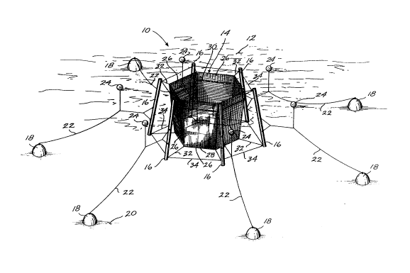
FIGURE 1 illustrates a representative embodiment of the spar buoy pen
system 10 situated in a body of water 12. The spar buoy pen system 10 includes a15 net pen 14, a plurality of elongate buoyancy members, in this case spar buoys 16
attached to the net pen 14, and anchors 18 resting on the sea floor 20. Each spar
buoy 16 has an anchor 18 attached to it with an anchor line 22. An auxiliary
float 24 is attached to each anchor line 22.
The net pen 14 is formed from six flexible walls Z6 and an attached flexible
20 bottom 28. The flexible walls 26 and bottom 28 are constructed of netting
material having a mesh size selected to restrict desired marine life or marine
organisms within the net pen 14. Because fish tend to swim together in large
groups~ the walls 26 taper inward at the bottom 28 to eliminate dead space and
make efficient use of the volume within the net pen 14. The net pen 14 has no
25 rigid structure in itself, relying on the attached spar buoys 16 and anchors 18 to
maintain the hexagonal configuration in a taut condition. Although the represen-tative embodiment illustrates the net pen 14 being formed of netting, a fabric-like
nylon or canvas could be used if desired.
The spar buoys 16 are elongate tubular columns that may be formed from
30 steel pipe or plast{c. The top and bottom are capped to provide a totally enclosed
watertight chamber within each buoy 16, creating buoyancy. Flotation devices
may be used with the buoys 16 to provide additional buoyancy. In addition,
ballasts in the form of some type of weight must be added near the bottom of
each spar buoy 16. In order for the invention to properly function, it is critical
35 that the center of buoyancy be above the center of gravity in each spar buoy 16 so
that the buoy 16 will float in a substantially upright position. The amount of
1 32 1 5 1 4
--4--
flotation and ballast used on each buoy will vary, depending on whether the buoy is
to be used fully submerged or whether a portion of the buoy is to remain above the
waterline. In the representative embodiment illustrated in FIGURE 1, the
waterline 30 is denoted by a darkened ring around the net pen 14.
Each spar buoy 16 is attached to the net pen 14 with an attachment line 32
at the top and bottom of the buoy 16. In addition, connecting lines 34 attach the
spar buoys 16 to each other at their tops and bottoms. While not critical to
practicing the present invention, these connecting lines 34 will maintain the spar
buoy 16 in their predetermined configuration, in this case, the hexagonal shape,even when the net pen 14 is removed. This is to iacilitate removal and replace-
ment of the net pen 14 in the open water without having to remove or replace thespar buoys 16.
Each spar buoy 16 is anchored at a predetermined location to the sea
floor 20 by an anchor 18. The anchor may be any suitable weighted article that
will remain stationary when placed on the sea floor 20. The anchor lines 22 are
shown attached to each buoy 16 at one or more points, and preferably at two
locations to stabili~e the buoy 16 in the water. To avoid a downward pull on thebuoys l~rom the anchor lines 22, an auxiliary float 24 is attached to each anchor
line 22 to provide an upward for¢e on the anchor line 22. This results in the
anchor line 2a exerting a lateral force on each buoy 16 to urge each spar buoy 16
laterally outward from the net pen 14 to thereby maintain the net pen 14 in a taut
conditlon.
Although the spar buoy 16 may be used in a substantially upright position,
this may be too flexible in some systems. It has been found that if the spar buoys
are dePlected from the vertical, they will reach a point where they are resistant
to further deflectlon because of increased righting moment. Depending on the
con~lguration of the particular spar buoy, thls angle has been found to be in the
range of 5 to 25, and, in the representative embodiment shown in FIGURE 1, is
prel~erably 15. Consequently, the anchors lô and the deflected spar buoys 16
cooperate to hold the net pen 14 in the hexagonal configuration and in a taut
¢ondition. To assist in maintaining the spar buoys 16 at an angle, the attachment
lInes 3a at the top of each buoy 16 are shorter than the attachment lines 32 at the
bottom of each buoy 16, and the anchor lines 22 are attached preferably below the
midpoint of each spar buoy 16.
} ~ 35 It is to be appreciated .hat, while a representative embodiment of the
invention has been shown and described, various changes may be made therein
1321514
--5--
without departing from the spirit and scope of the invention. For instance, the
net pen 14 may have a square, triangular or octagonal shape. Furthermore, the
net pen 14 may be replaced with a single flexible wall formed of either netting,fabric, or canvas. In addition, the spar buoy 16 may be used to hold platforms,
5 feeding systems, or storage containers. Similarly, masts, bird nets, predator nets,
and other devices may be attached to the top of each of the buoys 16.
As will be readily appreciated from the foregoing, the design illustrated
herein incorporates the use of spar buoys to shape and anchor net pens used to
grow fish for marketing, research or recreation. With the spar buoy anchored to
10 the bottom of the body of water and the net pen attached to the spar buoy at the
top and bottom, or along its entire draft, the spar buoy fixes the maximum
designed depth of the net pen vertically by virtue of its vertical stability. The
direction and magnitude of the anchoring forces acting through the spar buoy andthe net fix the final net pen configuration in length, width, and depth, and
15 maintain the net pen in a taut condition. The spar buoy net pen system can beused in any configuration, with as few as three for a triangular pen, or more buoys
arranged in a line may be used to form a wall, depending upon the ~inal net pen
configuration. A wall of netting or fabric can also be used as a current "blocker"
to reduce current and forces on a downstream pen or object in its "shadow." This20 use can be independent oi raising fish. In this system, the anchors 18, the spar
buoy lB, and the net pen 14 all form a flexible structure that can be used to hold a
variety oi marine species for aquacultural, recreational or research purposes.
Furthermore, the spar buoys make it possible to use a more solid, flexible wall
such as iabric or canvas because it will not be affected by currents or waves. The
25 spar buoy net pens may also be arranged in systems of nets that use one or more
spar buoys in common.