Note : Les descriptions sont présentées dans la langue officielle dans laquelle elles ont été soumises.
~ 3 ~ rl
MET~TOD AND APPARATUS FOR PRODUCING TUBULAR BODIES,
P~RTICULARLY FOR PACKAGING TUBES
Field o_ the ~nvention
The inverltion relates to a method for producing tubular
bodies, particularly for packaging tubes from a foil sheet having
an inside and an outside of weldable plastic. The foil sheet is
drawn from a supply roll and wound up continuously about a shaft
extending in its longitudinal direction to form a tube with
overlapping edges that are welded together. The invention also
relates to an apparatus for performing this method.
. .
Backaround of th_ Invention
Such apparatus is known from U.S. Patent 3,388,017.
However, it has been found in tubular bodies produced according
to this method that the outer edges of the weld seams have spots
which have not been welded and which tend to flake off or even
rip open. Particles of the material which have fla~ed off into
the interior thus can mix with the goods to be packaged and can
unduly contaminate it.
The realization that the spots tending to flaXe o~f are
formed by material pushed out of the weld seam during the welding
process has led to the present invention. The outer edges of
this pushed-out material prematurely cool because of their
minimal thickness and therefore can no longer come into welded
contact with the adjacent material.
. .
: `
~ 3 2 ~
It is accordingly the object of the invention to
device a method and an apparatus of the above type in which
the welded seam has no unwelded edges of squeezed-out
material. This object is attained as described hereinafter.
5According to the present inventlon, there is
provided a mekhod for producing tubular bodies, particularly
for packaging tubes from a foil sheet havi.ng an inside and
an outside of weldable plastic as well as rims extending
parallel to each other, comprising the steps of wrapping the
losheet continuously about a shaft having a longitudinal axis
to form on the shaft a tube having edges overlapping along
the rims to be sealed together by heat, pressing the
overlapping edges together between two endless belt means,
including an inner and an outer belt, with said outer belt
15overlying said innerbelt during a portion of the travel of
the belts to effect the said pressing of the overlapping
edges together, while moving the belt means relative to the
said shaft along the longitudinal axis, wherein a part of
the periphery of the tube thus formed and including the rims
20of the two edges is pressed at least partially into a
longitudinal outwardly open groove formed in the inner belt
after welding heat has been supplied and during the pressing
together.
The result of the method according to the
25invention is a perfect weld seam in a high-quality packaging
tube.
According to the present invention there is also
provided an apparatus for producing tubulax bodies,
particularly for packaging tubes from a foil sheet having an
30inside and an outside of weldable plastic as well as rims
extending parallel to each other, comprising a shaft having
a longitudinal axis, means for continuously wrapping the
sheet about said shaft in the direction of said axis to form
'
,.. .
:. :
.
.
1~2~
a tube from the sheet having edges overlapping along the
rims, mean6 for ~ealing the overlapping edges together, two
endle~ belt maans disposed to be driven relative to said
shaft along the longi-tudinal axis to press the overlapping
edges together, one of sald belt means being disposed during
at least a portion oE its travel on the inside of the tube
and having a longitudinal ~urface and a groove formed in
sflid surface for receiving at lea~t partly the overlapping
edges of the tube to be formed.
Preferably, the belts serving as welding tool~ are
made of ~teel. Their heat~ng by means o high frequen$y
radiation has the particular advantage that no other parts
are heated along with them. Since the~e belts preferably
~re of only small mass, they not only can be quickly heated
to the required temperture ~ut can al~o be quickly cooled,
thus achieving high e~iciency because of a great working
~peed.
BRIEF DESCRIPTION OF THE DR~WINGS
-
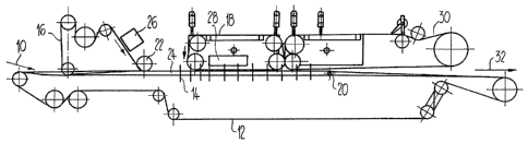
Fig. 1 shows an apparatus for producing tubulsr
bodies for packaging tube~, in a schemati¢ side view:
Fig. 2 show~ a tube forming region of the
apparatu~, on a larger ~cale than in Fig. 1;
Fig. 3 ~hows the tube forming region in cross
8 ection; and
Fig. 4 i8 a detail of Fig. 3.
.......... . . ... .. . .....
,., ~ , . ~, ., . , - :
. ..
,, - ,,~ ~ :
. ~ .. . .
. . \ ' - ';,, ;' . ' - -
~ 3 2 ~
Description of the Preferred Embodiment
The apparatus schematically shown in Fig. 1 is supplied
with a sheet of foil 10 drawn from a supply roll, not shown.
The foil sheet, comprising a plurality of layers, has an aluminum
layer that is embedded in at least two thermoplastic plastic
layers. The plastic layer that is to be oriented toward the
interior of the tube is oriented upward when supplied. In the
apparatus, the foil sheet is wound up continuously about a shaft
extending in its longitudinal direction to form the tube with
overlapping edges, which are welded together from the action of
heat. A belt 12 driven in rotation below the foil sheet is used
to unroll the foil sheet. By means of guide elements 14, the
belt 12 is curved upward at its two edges, so as to roll the foil ~ -
sheet resting on it about a mandrel extending in the longitudinal
direction above the belt 12.
The overlapping edges of the foil sheet lo , delimited by
rims which are parallel to each other, are pressed against one
another between an inner belt 16 and an outer belt 18. The two
belts 16 and 18 are used as pressing tools. The inner belt 16
extends along the aforementioned mandrel inside the tube that is
to be formed as far as a deflection roller 20, and then returns
inside the tube that is formed.
Before the inner belt 16 passes over a guide roller 22 to
reach the tube forming region 24, it may be inductively preheated
in its guide path by means of an apparatus 26. However,
preheating is.not absolutely required since a welding apparatus
28 provided in the tube forming region 24 serves to generate the
welding heat which inductively heats the aluminum foil embedded
in the foil sheets by means of hi~h frequency radiation. Heating
is regulated by metering the high frequency radiation such that
the thermoplastic layers of the foil sheet are heated to a
.:
,
~ ~ 2 . ~ ~ ~J
temperature su~ficient for welding. During and after welding
the overlapping ~dyes of the tubular body formed are pressed
against each other by the rotating belts 16 and 18. After
welding, the weld seam which has been foL-med is cooled by means
of a rotatingly driven endless cooling belt 30, while the
pressure aq~inst the inner belt lG is maintained. The positive
cooling permits higher working speed. The tubular bodies, welded
shut on the long sides and cut by means of a cutting apparatus not
shown, leave the described apparatus in the direction 32 and are
completed by the installation of a tube head and application of a
sealing cap.
Fig. 2 shows how the inner belt 16 is guided in the tube
forming region 24 along the aforementioned mandrel 34 as far as
the deflection roller 20 and back again. The upper run 16' of
the inner belt 16 rests on the mandrel 34, while the lower run
16 " is guided in a longitudinal groove 36 disposed in the
mandrel 34. The tube, shown in dashed lines, is indicated at
reference numeral 38.
Fig. 3 shows a cross section of the tube forming region
24 in a sector in which the foil sheet has already been rolled-up
in the form of a tube 38 by means of the belt 12. This drawing
clearly shows how the upper run 16' o~ the inner belt 16 is
guided on the mandrel 34, while the lower run 16'' is guided
inside the groove 36. The outer belt 18 i5 pressed against the
overlappiny edges of the formed tube 38 by the resilient welding
apparatus 28.
Fig. 4 shows a detail of the tube forming region 24. It
can be seem from this Fig. that the inner belt 16 has a
longitudinal groove 40 which serves to form the inwardly oriented
side of the tube seam of the tube 38. The longitudinal groove 40
gives a defined shape to the tube seam and prevents khe
:' ~
~3 ~6~
uncontrolled expansion during compression of the overlapping
edges 42 and 44 by limiting the flow of the molten material
during the welding process. The material is a thermoplastic,
particularly polyethylene, polypropylene or their co-polymers.
This weldable plastic forms the outer layers of the foil sheet
made into the tube 38. In addition to an aluminum layer embedded
between the plastic layers, the foil sheet can have further
layers, for example a paper 1ayer and adhesive layers for the
aluminum foil.
In an embodiment of the apparatus for the production of
tubular bodies from a foil sheet without embedded metallic layers
or with a very thin metallic layer, the two rotatably driven
belts 16 and 18 serving as welding tools are inductively heated
by high freguency radiation to the required welding temperature.
Heating can take place ahead of the tube forming region 24 ~Fig.
2) or~ for the outer belt 18, within this region by means of
correspondingly disposed heating devices. In such a case the
apparatus 26 is not used for pre-heating of the inner belt 16,
but for the complete heating of this belt to the temperature
required for welding. In such an embodiment of the apparatus,
heating of outer belt 18 can be accomplished by means of the
apparatus 28 either ahead of the tube forming region 24 (Fig. 2)
or within this region.
The rotatably driven belts 16 and 18 are preferably made of
steel if their heating is accomplished by means of high frequency
radiation. Ho~ever, if the welding heat is created exclusively
and directly in the aluminum layer of the foil sheet by means of
the apparatus 28, the belts 16 and 18 used as pressing tools can
also be made of, for example, polytetrafluoroethylene. In this
case the apparatus 26 is not required.
.
~ 9 ~,~ o ~ i
The apparatus 26 and 28 used for inductive heating in
general comprise a high frequency coil; the energy given of by it
is concentrated on the area to be heated. High frequency
generators of a known type are used or supplying these high
fre~uency coils.
~ ulti-layer foils of the type described and having a
metallic layer, particularly an aluminum layer, are known.
However, the apparatus described is al50 suitable for working of
the oil sheet consisting only o a single thermoplastic layer.
.. . . . .
,
.