Sélection de la langue

Search

Sommaire du brevet 1326718 

Énoncé de désistement de responsabilité concernant l'information provenant de tiers

Une partie des informations de ce site Web a été fournie par des sources externes. Le gouvernement du Canada n'assume aucune responsabilité concernant la précision, l'actualité ou la fiabilité des informations fournies par les sources externes. Les utilisateurs qui désirent employer cette information devraient consulter directement la source des informations. Le contenu fourni par les sources externes n'est pas assujetti aux exigences sur les langues officielles, la protection des renseignements personnels et l'accessibilité.

Disponibilité de l'Abrégé et des Revendications

L'apparition de différences dans le texte et l'image des Revendications et de l'Abrégé dépend du moment auquel le document est publié. Les textes des Revendications et de l'Abrégé sont affichés :

  • lorsque la demande peut être examinée par le public;
  • lorsque le brevet est émis (délivrance).
(12) Brevet: (11) CA 1326718
(21) Numéro de la demande: 551110
(54) Titre français: DIFFUSEUR D'AIR HAUT RENDEMENT POUR RESERVOIRS DE TRAITEMENT AEROBIE D'AEAUX USEES
(54) Titre anglais: HIGH YIELD AIR DIFFUSER FOR TANKS USED IN THE AEROBIC TREATMENT OF WASTE WATERS
Statut: Réputé périmé
Données bibliographiques
(52) Classification canadienne des brevets (CCB):
  • 362/9
(51) Classification internationale des brevets (CIB):
  • C02F 3/20 (2006.01)
  • B01F 3/04 (2006.01)
  • B01F 5/06 (2006.01)
  • C02F 3/12 (2006.01)
  • C02F 3/22 (2006.01)
  • B01F 15/00 (2006.01)
(72) Inventeurs :
  • PETRILLO, GIACINTO (Italie)
(73) Titulaires :
  • PETRILLO, GIACINTO (Italie)
(71) Demandeurs :
(74) Agent: GOWLING WLG (CANADA) LLP
(74) Co-agent:
(45) Délivré: 1994-02-01
(22) Date de dépôt: 1987-11-05
Licence disponible: S.O.
(25) Langue des documents déposés: Anglais

Traité de coopération en matière de brevets (PCT): Non

(30) Données de priorité de la demande:
Numéro de la demande Pays / territoire Date
23601 B/86 Italie 1986-11-06

Abrégés

Abrégé anglais


ABSTRACT OF THE DISCLOSURE
Diffuser comprising a cylindrical body inside which
a helical section is provided. At the base and at the top,
a sparger and a distributor respectively are foreseen.
Preferably a second sparger is foreseen at the top, around
the distributor. Each sparger consists of a hopper having
the major base provided with tongues that radially depart from
its periphery. Distributor comprises a truncated-cone portion
having the minor base made up of a conical element, openings
being provided both in the conical element and in the lateral
surface of the hopper. The diffuser is fixed to a suitable
support by means of tie rods held on the protruding edge of
the upper sparger.

Revendications

Note : Les revendications sont présentées dans la langue officielle dans laquelle elles ont été soumises.


The embodiments of the invention in which an exclusive
property or privilege is claimed are defined as follows:

1. A diffuser comprising a cylindrical body inside which
at least a helical section is provided, characterized in that a
sparger and a distributor are also provided at the base and the
top respectively and in that at the top, around the distributor,
another, second sparger is provided.
2. A diffuser as in claim 1, characterized in that the
sparger comprises a hopper having the major base provided with
tongues that radially depart from its periphery, and the minor
base provided with a protruding edge having openings for the
passage of tie rods fixing the diffuser, said minor base being
provided circumferentially with a seat capable of receiving an
end of the cylindrical body.
3. A diffuser as in claim 2, characterized in that the
distributor comprises truncated cone portion with the major
base open and the minor base provided with openings radially
distributed, further openings being provided along the lateral
surface of said portion.
4. A diffuser as in claim 3, characterized in that the
minor base of the truncated cone portion consists of a conical
element having the apex of the cone turned towards the inside of
the distributor.
5. A diffuser as in claim 3, characterized in that the
openings of the conical element have an almost trapezoidal
shape.
6. A diffuser as in claim 3, characterized in that the
openings, distributed along the lateral surface of the truncated
conical portion, are rectangular.
7. A diffuser as in claim 2, characterized in that the
lateral surface of the hopper is provided with openings.
8. A diffuser as in any one of claims 1, 2 or 3 charac-
terized in that major base of the truncated cone portion is
provided circumferentially with a engaging means inserted in a
seat of the hopper.


9. A diffuser as in claim 2, characterized in that the
protruding edge of the hopper is provided with reinforcements.
10. A diffuser as in claim 1, characterized in that the
cylindrical body consists of a plurality of sealed portions.
11. A diffuser as in claim 1, characterized in that it is
fixed to a support by means of tie rods.
12. A diffuser as in claim 11, characterized in that the
tie rods have the lower end fast with a perforated plate
inserted on the threaded rods protruding from the support, this
plate being fixed by means of a nut and washers.
13. A diffuser as in claim 12, characterized in that the
tie rods are mixed at the top of the protruding edge of the
upper sparger.
14. A diffuser as in any one of the previous claims 1-13,
characterized in that it receives the air to be diffused from a
horizontal conduit that runs near the bottom of the tank, the
conduit being fixed to the support.
15. A diffuser comprising a cylindrical body having a base
and a top, at least a helical section inside the cylindrical
body, a dispersing means at the base of the cylindrical body and
a distributor at the top of the cylindrical body, said dispers-
ing means comprising a frusto-conical skirt having a major base
and a minor base, and internal tongues that extend radially from
said frusto-conical skirt.
16. A diffuser as in claim 15, further comprising a second
dispersing means at the top of the cylindrical body, around the
distributor.
17. A diffuser as claimed in claim 15, wherein the minor
base of said dispersing means is provided with a protruding edge
having openings for the passage of tie rods therethrough to fix
the diffuser, and said minor base being provided circumferen-
tially with a seat capable of receiving an and of the cylindri-
cal body.
18. A diffuser as in claim 15, wherein the distributor
comprises a frusto-conical portion with an open major base and a


minor base provided with radially distributed openings, the
frusto-conical portion having a lateral surface with additional
openings provided therein.
19. A diffuser as in claim 18, wherein the minor base of
the frusto-conical portion of the distributor consists of a
conical element having an apex thereof directed toward the
inside of the distributor.
20. A diffuser as in claim 18, wherein the radially
distributed openings have a substantially trapezoidal shape.
21. A diffuser as in claim 18, wherein the additional
openings, provided in the lateral surface of the frusto-conical
portion, are rectangular.
22. A diffuser as is claim 17, wherein openings are
provided through the frusto-conical skirt of the dispersing
means.
23. A diffuser as in claim 18, wherein the open major base
of the frusto-conical portion of the distributor is provided
circumferentially with in engaging means to be inserted in a
seat of the second dispersing means.
24. A diffuser as in claim 17, wherein said protruding
edge is provided with reinforcements.
25. A diffuser as in claim 15, fixed to a support by means
of tie rods, said tie rods having a lower end fast with a
perforated plate inserted of threaded rods protruding from the
support, the plate being fixed by means of a nut and washers.
26. A diffuser as in claim 25, wherein the tie rods have
an upper end fixed to the protruding edge of the second dispers-
ing means.


Description

Note : Les descriptions sont présentées dans la langue officielle dans laquelle elles ont été soumises.


~32~718


~HI&a ~S~LD 3IR DIPPUSB~ FO~ T~RS ~S~D r~ T9~ aRRoBIc

.

: The present invention refers to the di~fusers used in tanks
for the aerobic purification of waste waters.


The Xnown diffusers are made in such a way so as to disperse
I the air blown into pipes running across the bottom of tanks
~ for aerobic treatment filled with waste waters.

Said diffusers are located at each air exit from the above
mentioned pipes. mess diffusers have ho~ever a reduced
e~icieacy becau~e the air îs distributed in bubble~ having a
dimension that i5 unsuitable for obtaining a uniform disper-
sion and ef~icient transfer of the oxygen to the li~uid; in
fact, the bubbles havlng big dimeDsions reach the surface
before an e~fsctive oxygen transfar to the waters to be
treated takes place.


~`

- ~ 2

~3267~

In order to improve the efficiency of the diffusers,
US-A-3,852,384 foresees that the blown-in air bubbles be
forced to follow a not rectilinear path, in particular a
spiral path, that increases the bubbles stay time in the
waters to be treated. me spiral path is obtained by
collecting the blown-in air in vertical cylindrical element~
where one or more helical baffles are provided so as to act as
guides for the bubbles. In this way the air and water mixture
~ollows a spiral path that prolo~gs the interface contact
between bubbles and liquid. The aforesaid cylindrical elements
are placed above the pipes running horizontally, near the
~ottom of the tank, these pipes being horizontal and
perforated in the lower part for the passage of the blown-in
air. Nevertheless, the yield has not reached optimum levels.


The object of the present invention is that of improving the
yield of the diffusers so as to obtain finely dispersed
b~bbles creating an efficacious transfer of the oxyyen to the
~aters to be treated.

,_ :
This aim is achieved by providing at the base and top of the
cylindrical body, comprising at its interior one or more
helical sections, a sparger and a distributor respectively.
me sparger consists o~ a hopper having the ~ajor base
provided with tongues that radially depart from i~ periphery
in order t~ catch the bubbles coming out from a horizontal
pipe running near the bottom of the ~ank and to cut the ~ass
of bubbles creating an additional turbolence. Th~ minor base


. . ~
~''' '
',
'

~ ~ -3-
132~7i8

of the sparger is provided with an edge protruding towards the
outside and openings for the passage of tie rods for the
a~chorage of the diffuser.


The minar base is circumferentially provided with a seat for
recei~ing the end of the cyli~drical body which is preferably
formed by a plurality of sections welded together.


The distributor placed at the top of the cylindrical element
comprises a truncated cone shaped portion with the ~ajor base
open a~nd the minor base provided with openings radially
distributed. Moreover, the lateral surface is provided with
further slots for the outlet of bubbles~


Preferably, the minor base consists of a tapered element with
the apex of the cona turned towards the inside of the
diffuser.


me distributor is fixed to the cylindrical body by means of
another hopper quite similar to the one of the sparger> witb
~he major base facing upwards so that this hopper is capable
of helpiny the discharge of the air-water mixture.


The described diffusers are uniformely distributed at the
bottom of the tank and anchored to supports~ in the shape of

concrete blocks, preferably by means of tie rods fixed with
bolts scre~ed on threaded rods protruding from the concrete
blocks, a psrforated plate that is inserted on the aforesaid
rod~ being foreseen at the lower end of the tie rod. At the
top, the tie rods are fixed on th~ protruding edge of the
second sparger ~hat ~urrounds the distributor, preferably with


~.

- 132~71~

nuts screwn on their threaded ends by interposing suitable
washers.


The present in~ention according to a preferred but not
limitative embodiment, is shown in the enclosed drawings, in
which:


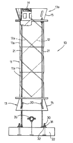
Pigure 1 shows a partially sectioned side view of the diffuser
anchored at its ~upp~rt;
Figure 2 shows a side view of the sparger;
Figure 3 shows a view of the sparger taken alo~g line 3-3 of
figure 2;
Figure 4 shows a ~iew of the sparger taken along line 4-4 of
figure 2;
Figure 5 shows a partially ~eotioned ~ide view of the
distributor;
Figure 6 shows an upper view of the distributor;
Figure 7 shows a detail of the sparg~r;
Figure 8 shows a saction of the tank with the diffusers
installed. -- ,


A diffuser 10 is shown in figure 1 comprising a cylindrical
body 11 containing tWQ helical sections 12 and 12a that cross
eaoh other J for~ing two ~piral canals for dischargiDg the
air-water mixture to be treated. The cylindrical body tl is
preferably made of a plurality of sections lla. me diffuser
i~ provided at its base with a sparger 13 ana at the top with
a di~tribu~or 14 which is held on the end of the diffu~er by

mean~ of a second ~parg~r 13a, the hopper 15 of which
laterally surround3 said distributor 14.


~3~1~71~

The sparger 13 (tha~ is quite similar to ~parger 13a) is shown
in detail in figures 2, 3 and 4. It is ~ade of a hopper 15,
the minor base of which has a periphery 17 provided with
tongues 16 perpendicular to said periphery 17. The minor base
is also provided with a protruding edge 18 having openings 19
for the passage of tie rods 21 ~figure 1) fixing the diffuser
10. The side surface of the hopper ~15) has further openings
~o a~ to allow the fixing tie rods 21 to extend
perpendicular to support 22 on whic~ they are fixed. This
protruding edge 18 also has reinforGements 23 cir~umferen-
tially disposed.


The minor base of hopper 15 is provided circumferentially with
a seat 28 capabl~ of recei~ing an end of the cylindrical body
11 .


Distributor 14 is ~hown in figures 5 and 6. It comprises a
truncated cone shaped portion 24, the mi~or base of which
consist~ in a tapered element 25 having the ape~ of the cone
turned towards the inside of portion 24. It can be notic~d
that th~ tapered alement is provided with openings 26, having
almoct ~rape~oidal shape. Furthermore, the tru~cated cone
sbap~d portion 24 is also laterally provided with rectangular
openings 27. These openings 26 and 27 are usea for ~he
distribution o th~ mixture of air-water to be treated.


Said truncated cone portion 24 is held at ~he end of the
cylindrical body 11 by means of a second ~parger t3a over-

turned with respect to the position of sparger 13 (see ~igure


~ ~5~ ~32~7~
1). An engaging means 29 iq foreseen inserted i~ seat 28 of
the minor base of the hopper 15, placed along the maJor base
of the truncated cone portion 24.


A detail of the protruding edge t8 is sbown in figurn 7; the
reinforcements 23 and the openings 19 for the pa~sage of tie
rods 21 are clearly visible.


Figure 8 shows a transverse ~ection of a tank used for the
aerobi~ treatment of waste waters; i~ said tank the diffusers
10 are placed and kept in their position on ~upports 22 in the
shape ~f con~rete hloc~5. me diffu~ers are plaoed on top of
conduits 35 for the blown-in airr that xun horizontally near
the bottom of the tank, these conduits 35 also being a~chored
to support 22 and provided in the lower part with open~ngs for
the air distribution.


Figure 1 shows a perforated fastening system in ~etail,
however it is obvious that other systems can b~ used. .~ie rods
21 have at the lower end a perforated plate 32 inserted o~ the
threaded rods 30 prot~uding fro~ ~upport 27, thc per ora~ed
plate being held in place by a ~ut 31 and washers. ~he tie
rods are fixed at the top to the protruding edge 18 of the
; ~ parger 13a by mea~s of nuts screwed o~ their threadsd ends
extendi~g from aperture~ 19.


me ~unc~ion of th~ diffuser is as follows: the air ~ubbles
delivered fro~ conduit 35 are caught and divided by D#ans of

the lowar sparger 13, thu they enter th~ cyli~drical ~cdy 1t
where they follow a spiral path mixi~g and interact w~th the
liquid to b~ treated, finally they reach distributor 14 and
exit finely divided.


Dessin représentatif
Une figure unique qui représente un dessin illustrant l'invention.
États administratifs

Pour une meilleure compréhension de l'état de la demande ou brevet qui figure sur cette page, la rubrique Mise en garde , et les descriptions de Brevet , États administratifs , Taxes périodiques et Historique des paiements devraient être consultées.

États administratifs

Titre Date
Date de délivrance prévu 1994-02-01
(22) Dépôt 1987-11-05
(45) Délivré 1994-02-01
Réputé périmé 2001-02-01

Historique d'abandonnement

Il n'y a pas d'historique d'abandonnement

Historique des paiements

Type de taxes Anniversaire Échéance Montant payé Date payée
Le dépôt d'une demande de brevet 0,00 $ 1987-11-05
Taxe de maintien en état - brevet - ancienne loi 2 1996-02-01 50,00 $ 1996-01-22
Taxe de maintien en état - brevet - ancienne loi 3 1997-02-03 50,00 $ 1997-01-17
Taxe de maintien en état - brevet - ancienne loi 4 1998-02-02 50,00 $ 1998-01-16
Taxe de maintien en état - brevet - ancienne loi 5 1999-02-01 75,00 $ 1999-01-18
Titulaires au dossier

Les titulaires actuels et antérieures au dossier sont affichés en ordre alphabétique.

Titulaires actuels au dossier
PETRILLO, GIACINTO
Titulaires antérieures au dossier
S.O.
Les propriétaires antérieurs qui ne figurent pas dans la liste des « Propriétaires au dossier » apparaîtront dans d'autres documents au dossier.
Documents

Pour visionner les fichiers sélectionnés, entrer le code reCAPTCHA :


Pour visualiser une image, cliquer sur un lien dans la colonne description du document. Pour télécharger l'image (les images), cliquer l'une ou plusieurs cases à cocher dans la première colonne et ensuite cliquer sur le bouton "Télécharger sélection en format PDF (archive Zip)" ou le bouton "Télécharger sélection (en un fichier PDF fusionné)".

Liste des documents de brevet publiés et non publiés sur la BDBC .

Si vous avez des difficultés à accéder au contenu, veuillez communiquer avec le Centre de services à la clientèle au 1-866-997-1936, ou envoyer un courriel au Centre de service à la clientèle de l'OPIC.


Description du
Document 
Date
(yyyy-mm-dd) 
Nombre de pages   Taille de l'image (Ko) 
Dessins 1994-07-21 4 129
Revendications 1994-07-21 3 166
Abrégé 1994-07-21 1 27
Page couverture 1994-07-21 1 17
Description 1994-07-21 6 207
Dessins représentatifs 2001-08-21 1 8
Taxes 1999-01-18 1 25
Taxes 1998-01-16 1 37
Demande d'examen 1991-03-25 1 73
Correspondance reliée au PCT 1993-11-01 2 43
Correspondance de la poursuite 1991-07-25 4 133
Taxes 1997-01-17 1 35
Taxes 1996-01-22 1 37