Note : Les descriptions sont présentées dans la langue officielle dans laquelle elles ont été soumises.
1 3 70539
ARTICULATED BRIDGE A~ A COIIPONENT OF A DETAC~ABLE
GANGWAY FLOOR PLATE BETWEEN TWO ARTICULATED RAILROAD CAR8
Articulated bridges of the general type to which this
invention relates are known (see for example German disclosure
documents 3 305 062 and 3 401 298)
Articulated bridges of this type offer the advantage that,
due to their diagonal adjustability, they do not impair the
operation of the railroad car, and enable passengers optimal
crossing from one car to another.
It is the objective of this invention to develop a practical
articulated bridge with respect to both application and
interconnectibility. By the term "application" is to be understood
the allocation of the gangway floor plate to an interconnected car,
or a car which is to be interconnected. These difficulties must,
in particular, be taken into consideration, because the bridge
must, on the one hand, be solidly and reliably supported by the car
and, on the other hand, the relative motion between the two
interconnected cars in the longitudinal direction of the cars must
be taken into consideration. The relative motion results from the
20 clearance occurring in the coupling device between the two cars and
is not to be absorbed by the bridge itself. The reason is that
this would considerably complicate the design of the bridge, which
is not desirable, because the bridge must be relatively versatile,
in order to absorb the remaining relative motions occurring
between the two cars.
By the term "interconnectibility" is meant that two bridges,
1 332539
Z
which j ointly bridge the gap between interconnected cars, must be
detachably interconnected at the center between the two cars. Such
a detachable connection or coupling is essential in order to
interconnect or detach cars within the train from one another, and
to employ those cars as rear carriages in two different trains.
In the latter application, the articulated bridges are folded
upward. In addition, it is necessary to so provide this
interconnectibility that the front ends of two cars can be
interconnected irrespective of the seo,uence in which a multitude
lO of cars is arranged within a train. To achieve the objective of
this invention, the invention deals with the potential of
connecting or supporting gangway foot plates in accordance with
the aforesaid prior art.
me present invention provides an articulated bridge as a c~conent of a detachable
gangway floor plate between two articulated interconnected railroad
cars, the bridge being provided with several elongated bridge
elements extending transverse to the direction of the bridge, the
articulated extremities of the bridge being defined by the side
walls of a frame approximately following the contours of the
20 bridge, one end section of the bridge being designed for attachment
to one of the two interconnected railroad cars and the other end
section of the bridge being designed for attachment to the
corresponding end section of an articulated bridge of sections
running in the transverse direction of the bridge, characterized
by the end section of the frame running in the transverse direction
of the bridge, which is allocated to one of the interconnected
railroad cars, being carried by a carriage which is adjustable
,~
- ZA - ~ 33? 53q
in a trough of the railroad car, in the longitudinal
direction of the bridge, in a path of positioning movement derived
from the longitudinal clearance of the coupling between the two
railroad cars.
In the following description, the invention is explained in
detail with reference to the accompanying drawings. In the
drawings:
Fig. 1 shows one end of an articulated bridge in accordance
with this invention, which faces two interconnected cars;
Fig. 2 shows the other end of an articulated bridge in
accordance with this invention, which is coupled with the
corresponding "other" end of a second articulated bridge of a car
coupled with the first car, the second articulated bridge also
being in accordance with this invention;
Fig. 3 shows a top view of the bridge shown in Fig. 2, on a
different scale;
Fig. 4 shows a top view of the bridge shown in Fig. 2, again
_ _ _ _
/
1 33~5~'~
on a different scale;
Fig. 5 shows a sectional view taken along line A - A in Fig.
3; and
Fig. 6 shows a sectional view taken along line B - B in Fig.
4 ;
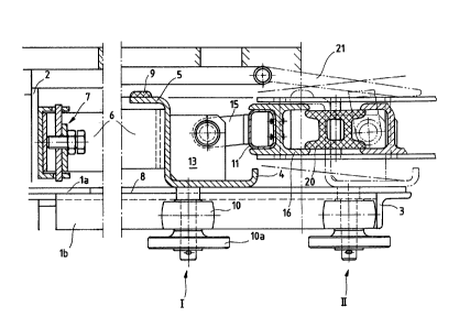
At the front end of a railroad car, a transverse trough is
attached to the bottom frame of the car, or embedded therein at the
front end. The trough comprises two lateral angular rails 1 (Figs.
1 and 5), a relatively high rear wall 2 interconnectin~ the angular
10 rails 1, and an angular rail 3 which also interconnects the two
angular rails 1. This is a welded sheet metal construction which
by means of the rear wall 2 is detachably or, by conventional
means, permanently affixed to the railroad car.
The trough carries an adjustable carriage 4, in the
longitudinal direction of the car, whose path of positioning
movement results from the travel of the spring within the coupling
which is allocated to the railroad car in the usual manner and with
which the car is connected with the next car. The carriage 4, when
viewed from its side, has a U-shaped cross-section with a high rear
20 wall and a lower front wall. At the upper extremity of the rear
wall, there is attached a horizontal gib 5 tuned toward the
outs ide .
The positioning movement of the carriage 4 is limited toward
the front by the angular front rail 3 of the trough. The
positioning movement of the carriage toward the wall 2 is
counteracted by a leaf spring 6 whose center is retained in a
1 332539
bearing 7 at the rear wall 2 of the trough 1-3 and whose two
concave extremities rest against the carriage 4. The leaf spring
6 is so designed and arranged that it is increasingly loaded as the
carriage 4 moves away from the wall 2 of the trough. In order to
prevent overloading of the spring 6, the gib 5 can be so balanced
that at one end off the path of positioning movement of the
carriage 4 it pushes against the rear wall 2 of the trough, just
before the spring 6 reaches its maximum load.
For reducing sliding friction, the horizontal legs la of the
10 angular rails within the area of positioning movement are lined
with a friction-reducing lining 8 (Figs. 1 and 5). At the
horizontal legs la of the angular rails 1, the carriage is
supported by the linings 8. In order to prevent the carriage 4
from tilting around its longitudinal axis, a sliding pad 9 is
attached at each extremity of the gib 5, and by these pads at both
extremities of the gib 5 the carriage is supported by an upper
plate 5a which also interconnects the angular rails.
The lateral guiding of the carriage 4 is aided by rollers 10.
The front end of each roller is carried at the underside of the
20 carriage, is freely rotatable around a vertical axis, and is
supported by a downward section lb at one of the lateral rails 1.
At the lower extremity of the vertical axis a disc lOa is arranged
at a specific distance so that the disc comes to rest against the
underside of the section lb of the respective lateral angular rail
1, if the carriage 4 in this area is adjusted unduly high.
A rigid low frame is carried by two bearings staggered in
1 33~53q
transverse direction of the car, the frame being provided with a
rear transverse tube 11. Each bearing comprises two parallel end
shields 12 and 13 between which a transverse journal 14 is carried.
A tongue 15 is pivoted on journal 14, the front end of the tongue
being connected to the transverse tube 11. The rear extremities
of the end shields 12 and 13 are affixed to the rear wall of the
carriage 4.
On the transverse tube 11, there is affixed the first of
several successive bridge elements 16. Each of these bridge
10 elements is an I-section. The two rear flanges of the first bridge
element engages the top and bottom of the transverse tube 11, or
its parallel top and base surface, and the rear surface of the web
of the bridge element rests against the front of the two parallel
side walls of the transverse tube 11, which appears rectangular
when viewed in cross-section (Fig. 1).
The bridge elements 16, which are similar in cross-section and
length, are held at both ends between the flanges of the side walls
17 of the frame, which are I-shaped when viewed in cross-section
(Figs. 2 and 5). The side walls 17 of the frame have horizontal
20 flanges located opposite each other, so that the bridge elements
can be held between those flanges. At their extremities, the
flanges of the bridge elements are slightly longer than the webs,
and are provided with slits 18 (Figs. 3 and 4). The bridge
elements, by means of slits 18, grasp the journals 19 held in the
flanges of the side walls 17. By this means, the bridge elements
16 can be hinged between the flanges of the side walls 17. The
1 33253q
bridge elements preferably are comprised of aluminum profiles whose
surface is provided with a friction-increasing lining.
Between each of the successive bridge elements 16, an
intermediate element 20 is held. The intermediate elements
basically have the same cross-section as the bridge elements 16;
however, they are preferably made of a plastic material. For this
reason, they have a correspondingly greater wall thickness, and the
web is double-walled or developed as a chamber profile. In
addition, the intermediate elements are shorter than the bridge
10 elements, so that they can be retained in the space between the two
flanges of a bridge element. Also, the elements are provided with
slits at their extremities, and each slit grasps a journal of a
side wall 17.
In order to avoid the formation of steps in the end section
of the articulated bridge relating to the railroad car, a
transition plate 21 (Fig. 1) is swivel-mounted at the railroad car,
the open end of said transition plate being loosely supported by
the bridge. The articulated bridge, which faces away from the
railroad car, is placed over a non-abrasive lining 22 upon a
20 support traverse 23, which is a component of the central buffer
coupling between this and the succeeding railroad car. The
succeeding railroad car carries a similar bridge in the same
manner, and in the area of the center buffer coupling both bridges
are detachably coupled,, so that both halves form a continuous
gangway f loor plate .
In order to detachably couple the two brld~e halve~ wlth on~
~_ 1 33253'~
another, the two bridge halves are designed as follows. The two
bridge halves at one side of a perpendicular plane passing through
the railroad car will be described, the configuration on the other
side of the longitudinal plane being similar. The sections
comprising "one" side of "one" of the bridge halves are also found
on the other side of the longitudinal plane of the "other" bridge
half and vice versa, so that the railroad cars can be
interconnected in any alternating order.
At the last bridge element 16, a tube 24 (Fig. 6), which
10 appears rectangular when viewed in cross-section, is attached, the
tube running parallel to the bridge element, the latter extending
approximately to the aforesaid vertical longitudinal plane, but not
projecting beyond that plane. Tube 24 accommodates an interlock
25 (Fig. 4) which is adjustable under the influence of a spring 26
or against the action of the spring. At its end near the side wall
of the car, the conical head 27 of interlock 25 projects into an
interlock holding fixture 28 allocated to the other end of the
bridge half. Fixture 28 is a punched metal plate supported at the
other half of the bridge. In this interlocking position of the
20 interlock 25, spring 26 is completely or largely released.
In order to separate the two bridge halves from one another,
the interlock 25 must be pushed out of the interlock holding
fixture 28. For this purpose, a finger 30 projects into a pocket
29 of the interlock 25. ,Finger 30 is located on a vertical journal
31, which is rotatable around its longitudinal axis, so as to
swivel the finger 30 and thereby 61ide the lnterlock 25. In or~er
~ 33253q
to rotate j ournal 31, it is shaped at its upper extremity in the
form of a square which can be engaged by a suitable key fitted
through an aperture in the upper flange of the last bridge element.
The journal 31 is fitted on to a second tube 32, corresponding to
the tube 24 and located, between the tube 24 and the bridge element
16 .
The articulated bridge in accordance with the invention offers
a multitude of advantages. The transverse displacement between the
two railroad cars can be absorbed by the articulated bridge,
10 because the bridge is adjustable in diagonal directions. The
displacement is limited when one of the side walls 17, by means of
a rubber buffer 33, comes to rest at the external vertical section
lc of trough 1. The vertical displacement between the two railroad
cars can be absorbed by the joints. These joints also enable the
bridge to be folded upward toward the end wall of the car.
Longitudinal displacements, occuring at a distance between two
interconnected cars due to couplng clearance, are absorbed by the
troughs through the longitudianl movement of the carriages of two
interconnected bridges. The two bridges are centered by means of
20 the springs 6 located in the center between the two cars. In Fig.
1, one of the end positions of the bridge is designated as I, and
the other as II.