Note : Les descriptions sont présentées dans la langue officielle dans laquelle elles ont été soumises.
1333~2
FABRY-PEROT INTERFEROMETER
The invention relates to Fabry-Perot
interferometers.
A typical Fabry-Perot interferometer comprises a
pair of substantially parallel reflective surfaces which
are spaced apart to define a gap, at least one cf the
surfaces being movable relatively to the other to vary
the size of the gap. In use, radiation comprising a
number of different wavelengths impinses on the
interferometer and passes into the gap and is then
reflected between the two reflective surfaces.
Constructive and destructive interference takes place
leading to certain well definec wavelengths being
transmitted through the interferometer while the
remaining wavelengths are not transmitted. In typical
Fabry-Perot interferometers a series of well defined
transmission peaks are obtained corresponding to
wavelengths which are transmitted, the wavelengths at
which the peaks are situated being adjustable by varying
the width of the gap.
Fabry-Perot interferometers have been used to
large extent to define laser cavities but also finc
widespread use as multiple wavelength filters.
It is important that the reflective surfaces of the
interferometer are as parallel as possible and it is also
desirable to be able to char.ge the separation between the
reflective surfaces over a wide range.
The most common form of Fabry-Perot interferometer
currently in use comprises two glass flats securely
mounted on G stable support with facing surfaces of the
flats being highly polished and having suitable coatings
to define the reflective surfaces. The size of the gap
may vary between one millimetre and several centimetres
anZ is varied by using microadjusters and/or
piezoelectric translation elements. This is a cumbersome
1333152
and expensive arrangement and has a relatively large
overall size, typically in the order of inches.
Another form of Fabry-Perot interferometer comprises
a single solid glass flat, the opposite faces of which
are polished and suitably coated to define the reflective
surfaces. The only practical way in which the spacing or
gap between the surfaces can be changed is by heating the
flat to cause thermal expansion. This construction
suffers from the disadvantage that the variation in
separation obtair.able is small and the disadvantage that
it is very difficult to obtain accurately parallel
surfaces.
In accordance with the present invention, in a
Fabry-Perot interferometer one of the reflective surfaces
is provided on a diaphragm ~lounted by a hinge assembly to
a support.
This invention improves upon the known
interferometers by making use of a diaphragm to provide
one of the reflective surfaces and mounting the diaphragm
by a hinge assembly to a support so that the position of
the diaphragm can be easily changed. This enables the
size of the gap to be eas~ly and rapidly changed. For
example, the interferometer can be used to demultiplex an
incoming wavelength divisicn multiplexed signal in which
a number of different channels are carried by different
wavelength signals. In this application, it is often
necessary to retune rapidly from one channel to another
and this can easily be achieved using an interferometer
according to the invention.
Preferably, the diaphragm and the hinge assembly are
intesral with the support. This leads to a compact and
secure construction which is much cheaper to manufacture
than known devices and involves far fewer components.
Convenientiy, a single crystal such as silicon is
- 35 used for the support, diaphragm and hinge assembly. This
1 ~ 3 ~ 1 5 2
is particularly advantageous since conventional
micromachining techniques such as anisotropic etching can
be used to form the hinge assembly and diaphragm. Such
techniques include masking and etching and laser etching.
(It is also believed that these techniques will enable
the orientation of the reflective surfaces to be
accurately controlled thus making it easier to arrange
the one reflective surface parallel with the other.)
The interferometer may further comprise control
means responsive to control signals to cause the
diaphrag~, to move relatively to the support towards and
away from the other reflective surface. The contrGl
means may comprise a pair of electrodes for connection in
to a control circuit for generating an electrostatic
field wherein the position of the diaphragm correspcnds
to the strength of the field.
The interferometer could be used as a pressure
sensor due to the sensitive mounting arrangement of the
diaphragm. For example pressure changes due to acoustic
2~ fields would cause the diaphragm to oscillate thus
modulating a sing e wavelength incident Gptical wave.
This would fir.c application in microphones and
hydrophones.
Typically, the other reflective surface may be
provided on a facing surface of a superstrate positioned
adjacent the substrate. The superstrate may conver.iently
be formed of glass.
Preferably, the superstrate and substrate are
connected together via an intermediate spacer layer since
this will form a compact constructior..
As has previously been mentioned, the interferometer
may be used to demultiplex a wavelength division
multiplexed signal or to define a laser cavity. In the
latter case, a suitable gain medium would be positioned
between the reflective surfaces.
1333~52
Another application for which interferometers
according to the invention are particularly applicable is
in the construction of an optical beam modulator. The
use of a diaphragm enables the size of the separation of
the reflective surfaces to be rapidly changed, for
example at kilohertz rates. If a single wavelength beam
is incider.t on the interferometer, this can be modulated
by moving the diaphragm between two positions at one of
which the beam is transmitted and at the other of which
the beam is not transmitted.
In another application, the interferometer can be
used as a wavelength switch when beams of radiation
centred on two different wavelengths are incident on the
interferometer. ~y suitably choosing the size of the
gap, it can be arranged that one wavelength is
trznsmitted while the other is back reflected.
An example of a Fabry-Perot interferometer according
to the invention will now be described with reference to
the accompanying drawings, in which:-
Figure 1 is a cross-section; and,
Figure 2 is a plan; and,
Figures 3 anc 4 illustrate the performance of the
interferometer with two different gzps.
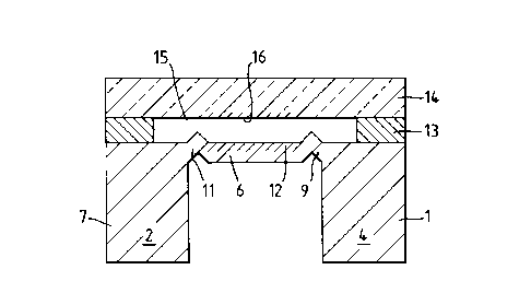
The interferometer shown in Figures 1 and 2
comprises a sinsle crystal silicon substrate 1 having
four integral walls 2-5 forming a square. A diaphragm 6
is suspended fro~ upper portions of the walls 2-5 within
a central aperture 7 by a hinge assembly comprising four
bridges 8-11 each having a typical length in the range
1-5 mm. The hinge assembly is integral with both the
substrate 1 and the diaphragm 6. This structure is
formed by anisotropically etching the substrate 1. A
semi-reflective coating 12 is providea on a polished
upper surface of the diaphragm 6.
1333152
A spacer layer 13 having a typical thickness in the
range 5-50 ~m is grown around the perimeter of the
substrate 1 and a glass superstrate 14 is bonded to the
spacer layer 13. An air gap 15 is defined between the
superstrate 14 and the substrate 1. A portion 16 of the
surface of the superstrate 14 facing the diaphragm 6 is
polished and coated with a reflective coating to define a
secon2 reflective surface.
A pair of transparent electrodes are coated on the
surfaces 6, 16 and are connected to a control circuit
(not shown). Suitable electrodes may be made from Indiu~
Tin Oxide. One electrode is indicated at 17 coupled with
a cor.tact pad 18. In a modification (not shown) one
electrode could be on the surface of the diaphragm
opposite the surface 6.
In use, a beam of radiation impinges on either the
glass superstrate 14 or the underside of the diaphragm 6
and passes into the air gap 15. Internal reflection of
the beam takes place in the air gap 15 due to the
reflective surfaces 12, 16 resulting in constructive and
destructive interference of the different wavelengths in
the incoming beam. The result of this is that certain
beams of very narrow bandwidth are transmitted through
the air gap into the opposing substrate or superstrate
while the majority of the wavelengths are back reflected.
The size of the air gap 15 (ie. the distance between
the reflective surfaces 12, 16) can be adjusted by
varying the electrostatic field generated between the
electrodes. This causes movement of the diaphragm 6
3Q relatively to the remainder of the substrate 1. A change
in the size of the air gap causes a change in the
wavelengths which are transmitted.
The use of a single crystal as the substrate is
particularly advantageous, as previously mentioned, since
the walls 2-4, diaphragm 6, and bridges 8-11 can be
6 I33~
integrally formed by conventional micromachining
techniques. This leads to a very cheap product compared
with previous interferometers and also enables small air
gaps to be defined. It should be noted that the
interferometer would need no adjustment or setting up
since the cavity gap would be defined during manufacture.
If desired, the size of the gap can be monitored by
providing capacitor plates on the facing surfaces cf the
superstrate 14 and the bridge 6 and monitorins the
capacitance between the plates. This could very ~imply
be achieved by making use of the electrodes as capacitor
plates while a voltage is applied between them.
Furthermore, due to their small size, a nu~ber of
Fabry-Perot interferometers could be fabricated onto a
single wafer which would be particularly useful in
optical communication fields.
~ igures 3 and 4 illustrate graphically examples of
the transmission characteristics of the interferometer
with gaps of 12~m and 48~m respectively. In each case
the reflectivity of the facing surfaces is 0.8 although
it could be as high as 0.999.
The device may find application, inter alia, as
wavelength selective element in long external cavity lasers.