Note : Les descriptions sont présentées dans la langue officielle dans laquelle elles ont été soumises.
1 337608
Title
Floating Lip Seal With Reinforced Flexible Portion
Background of the Invention
This invention relates to shaft seals, and more particularly
to structures for accnmmoA~ting radial shaft movements associated
with runout and mis-alignment eccentricities.
Numerous prior art sealing designs are provided for
conditions of high shaft runout and mis-alignment in environments
such as crankcase housing bores having shafts extending
therefrom. When severe, such conditions cause premature failures
of typical sealing systems. Many designs include flexible
sections which connect lip type sealing elements with rigid case
supports normally affixed to the housing bores. The flexible
sections provide a floating capability with respect to the
sealing lip for permitting radial movement of a shaft relative to
the rigid case support without severe leakage, particularly where
extreme eccentricities allow for high shaft runouts over
substantial periods of time.
Most of these systems, however, lack stability under extreme
runout conditions, wherein, notwithst~n~ing the flexibility of
the connective member between the rigid case support and the lip
sealing element, there is a need to control or at least curtail
some of the dynamic movement associated with the flexible
portion. Such control of dynamic seal lip movement would enhance
lip contact with the shaft.
Summary of the Invention
The improved lip seal assembly of the present invention
incorporates a convoluted flexible section which provides a
radial float capability sufficient to hold and maintain the
primary sealing lip in contact with the shaft under
eccentricities in excess of 0.060 inches.
1 337608
In addition, the present invention provides a means for
protecting the primary sealing lip via the use of a dirt lip
angled away from the oil side of the seal. In one preferred
form, the invention also provides a bearing member comprising a
low friction cylindrical body which closely engages the shaft at
ali imes, preferably formed of polytetrafluoroethylene. The
latter bearing member is preferably positioned intermediately of
the primary sealing lip and the dirt lip, whereby the dirt lip
may protect both the bearing surface-shaft interface as well as
the primary lip-shaft interface.
The present invention provides a rigidity reinforcement in
the flexible portion, the flexible portion defining a convoluted
cross section having a plurality of annuli adjoined by reverse
bends. One of the reverse bends includes an integrally molded
annulus formed of a less elastic material than that of the
annuli, such as a plastic. In the same preferred form, the
reinforcement annulus has a circular cross section.
Also in the present invention, each successive reverse bend
away from the case support has a thickness less than that of the
next adjacent reverse bend. This provides for a generally more
optimal flexibility pattern than if the reverse bends have equal
or uniform thicknesses. The seal assembly of the present
invention will therefore accommodate a substantial amount of
eccentricity, while avoiding the typical sealing lip distortion
on the "high" side of the shaft with concurrent loss of sealing
contact on the opposite or "low" side.
Brief Description of the Drawings
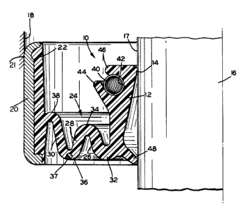
Figure 1 is a fragmentary half-cross section view of a
floating lip seal of the present invention having a reinforced
flexible portion.
Figure 2 is a similar view of an alternative ~mho~iment.
1 337608
Detailed Description of Preferred Embodiments
Making reference initially to Figure 1, a floating lip
seal assembly 10 includes an elastomeric annular primary body
portion 12 which contains a primary sealing lip 14. The lip 14
is adapted for continuous contact with a shaft 16, and
circumferentially engages the outside diameter (O.D.) 17 of the
shaft, as shown. The lip seal assembly 10 is disposed for
insertion into a bore 18, such as that of an automotive crankcase
(not shown), by means of a rigid case shell 20 to which the
elastomeric body of the assembly 10 is molded. In the preferred
form, the rigid case shell 20 is of a metallic material. For
purposes of frictional securement of the assembly 10 within the
bore 18, the outside diameter 21 of the case shell 20 is sized so
as to provide an interference fit with the bore 18.
An elastomer inner shell 22 is integrally molded directly to
the shell 20, and the primary body portion 12 is an integral part
of the shell 22, being connected to the inner shell 22 via a
flexible portion 24.
The portion 24, to which this invention particularly
relates, is formed of a plurality of integrally formed annuli of
the same elastomer material as that of the inner shell 22 and the
primary body portion 12. In the preferred ~mho~im~nt in Figure
1, there are three annuli: a first annulus 26, a second annulus
28, and a third annulus 30. The annuli are all connected by a
plurality of reverse bends; a first reverse bend 32 integrally
connects the primary body portion 12 with the first annulus 26.
The second reverse bend 34 connects the first and second annulus
26 and 28 respectively. The third reverse bend 36 connect the
second and third annuli 28 and 30. Finally, a partial reverse
bend ~8 connects the third annulus 30 with the elastomer inner
shell 22.
In the preferred form, the various reverse bends become
successively smaller in radial thickness as their dist~nces from
the primary body portion 12 become greater. Thus, the partial
reverse bend 38 is smaller in thickness than the third reverse
-
1 33~6~8
bend 36. Similarly, the third reverse bend 36 has a thickness
less than that of the second reverse bend 34. Finally, the
second reverse bend has a thickness less than that of the first
reverse bend 32. In the preferred form, each successive reverse
bend may have a thickness approaching 60-75 percent of that of
each adjacent reverse bend closer to the primary body portion 12.
This relationship has been found to provide a more optimal
dynamic movement of the flexible body portion during high
frequency vibrations under conditions under which total
eccentricities approach one hundred thousandths of an inch.
An additional feature provided by the present invention
relates to the relative angular flexibility of each reverse bend
as related to the particular pair of annuli associated therewith.
Thus, for example, the reverse bend 36 will have a certain amount
of annular flexibility which will affect the torsional movements
of second and third annuli 28 and 30 with respect to each other
about the reverse bend 36. Thus the annular stiffness of the
reverse bend will affect the initial dynamic properties of the
latter pair of annuli, and hence the overall performance of the
lip seal-shaft interface under conditions of extreme eccentricity
or shaft runout.
For this purpose, a reinforcement ring 37 is formed of a
preferably high temperature plastic material molded into the
elastomeric flexible portion 24 as shown at the time of
manufacture of the assembly 10. Although the preferred
embodiment shown in Figure l incorporates the reinforcement ring
37 at the third reverse bend 36, this invention is not limited to
such placement of the reinforcement ring, but envisions potential
placement of the ring or rings at other reverse bend locations
for desired dynamic control of the primary sealing lip 14 on the
O.D. 17. In addition, this invention contemplates that the
reinforcement ring 37, which imparts torsional rigidity to the
particular bend of its location, may be formed of other materials
besides plastic, such as, for example, steel or certain other
materials suitable for reinforcing stiffness of elastomers.
1 33760g
Also, the preferred cross-sectional diameter of the ring 37 is in
the range of 25 to 50 percent of the reverse bend thickness.
As will be apparent in Figure 1, the primary sealing lip 14
is placed under a slight static compression load against the
shaft 16 by provision of a garter spring 40 as is conventional in
~he art. The garter spring 40 is ret~i~e~ within a groove 42
having annular projections 44 and 46 which engage the majority of
the cross section of the garter spring as shown. In addition,
and as earlier indicated, the first preferred ~mho~;ment of
Figure 1 includes a dirt lip 48 for protecting the life of the
primary sealing lip. In the preferred form, the lip 48 is angled
away from the primary sealing lip, as shown. Finally, the
primary sealing lip may include a helical rib tO enh~nce the oil
leakage control capabilities of the lip 14.
Referring now to Figure 2, an alternative Pmho~iment of the
lip seal assembly 10' is shown, which is similar in most respects
to the assembly 10 of Figure 1. The alternative emho~iment of
Figure 2, however, includes a cylindrical bearing member 50
interposed between the primary sealing lip 14' and the dirt lip
48'. The latter bearing ~mher provides a means of enhAncing the
ability of the sealing lip 14' to follow ..ov_..ent of the shaft
16' under severe eccentricities. In the preferred form, the
bearing member includes a cylindrical bearing liner 52 as shown,
preferably of a polytetrafluoroethylene material. The latter
material is preferred for its particularly low coefficient of
friction.
It will be noted in reference to the presently described
preferred Pmho~;me~ts that the dirt lip as described and shown
comprises a line contact with the shaft, whereas the bearing
member 50 comprises a surface contact with the shaft. It is
conceivable, however, that there may be alternative designs which
provide for line contact of the shaft by the bearing member and
surface contact by the dirt lip. In addition, there may be
embodiments wherein a plurality of dirt lips may be employed, or
even a plurality of bearing members. All of such alternative
- 1 ~376~8
embodiments, as well as numerous others, are envisioned to be
covered by the following claims, to the extent that they may fall
within the spirit and scope thereof.