Note : Les descriptions sont présentées dans la langue officielle dans laquelle elles ont été soumises.
3Q3~
BACKGRO~ND OF THE INVENTION
Field of the Invention
This invention relates to slide fasteners and more
particularly to a separable type slide fastener suitable for
use in jackets and the like garment article to facilitate
the removal thereof from the user. The invention is more
specifically directed to a separable slide fastener of the
type carrying coupling element rows in a meandering or zig-
zag formation.
Prior Art
Various separable slide fasteners have been proposed,
a typical example of which is provided with a separable
bottom-end-stop assembly including a pin member attached to
one of a pair of fastener stringers and a socket member to
the other stringer, the ping being releasably engageable
with the socket to join the respective lower ends of the
stringers. Such known separable bottom-end-stop assemblies
were successful when applied to slide fasteners carrying
coupling elements of a helical coil structure, but were not
very satisfactory when applied to slide fasteners having
meander or zig-zag shaped continuous coupling elements
mounted astride both sides of the fastener tapes. This is
because more stresses would be required for the latter type
of fastener to bend or flex along an axis vertical to the
plane of the fastener with the results that the fastener
stringers once coupled together are, when such stresses are
exerted, apt to separate unintentionally starting with the
2~
first terminal or lowermost one of the coupling elements
immediately adjacent the bottom-end-stop assembly. Such
unintentional separation of the stringers is often referred
to as "chain crack".
To cope with the above "chain crack" problem, there
has been proposed a separable slide fastener, as disclosed
in U.S. Patent 3,377,668, in which a separable
bottom-end-stop assembly has a pin member on one stringer
and a socket with pin on the other stringer, the pin member
including a projection arranged to come under and engage the
lower portion of a coupling head of the lowermost coupling
element contiguous with the socket pin. This arrangement is
effective in combatting lateral pull on the fastener but not
quite for overcoming stresses tending to flex the fastener
laterally across inasmuch as the projection merely rests
underneath the coupling head of the coupling element. To
further assure retention of the lowermost element with
respect to the projection of the pin member, there is
provided in the socket pin a groove configured to receive a
corresponding rail-like portion of the pin msmber with a
tight interlocking fit. This arrangement is not only so
much costly but also would involve increased resistance to
sliding coupling and uncoupling of the pin and socket
membersO
SUMMARY OF THE INVENTION
It is therefore the primary object of the present
invention to provide a separable slide fastener with a
. . ,
,'
2~
separable bottom-end-stop assembly having a pin and a socket
member which can be engaged and disengaged with utmost ea~e
and which incorporates structural feature such that the
lowermost fastener element can be steadily retained in place
against sever lateral pull and bending stresses which would
otherwise cause "chain crack".
A more specific object of the invention is to provide
a separable bottom-end-stop assembly which is suitable for
use with a slide fastener having a meander or zig-zag
formation of fastener elements.
According to the invention, there is provided a
separable slide fastener comprising a pair of opposed
stringers each including a tape and a row of coupling
elements secured along one longitudinal edge of the
tape, and each of the coupling elements having a
coupling head with upper and lower hook portions,
a slider movable reciprocably on and along the pair o
stringers, and a separable bottom-end-stop assembly
comprising a socket member fixedly connected to a lower
end portion of one the stringer, a socket pin member
integral with and projecting from the socket member and
a guide pin member fixedly connected to a lower end
portion of the other the stringer and releasably engageable
with the socket member, the guide pin has a bulged upper
end portion which is bevelled to provide a cross-sectionally
semi-circular opening for receiving the coupling head of
a lowermost terminal element in the row of elements on the
stringer.
The above and other objects and features of the
invention will become manifest from the following detailed
description of certain preferred embodiments taken in
conjunction with the accompanying drawings.
BRIEF DESCRIPTION OF THE DRAWINGS
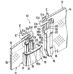
FIG. 1 is a perspective view of a segmentary bottom
end portion of a separable slide fastener, showing a
separable bottom-end-stop assembly;
FIG. 2 is a modified form of a portion of a guide pin
member constituting part of the stop assembly;
FIG. 3 is a transverse cross-sectional view of the
guide pin member;
FIG. 4 is a plan, partly sectional, view of a bottom
end portion of the fastener of FIG. 1 shown in closed
disposition;
FIG. 5 is a transverse cross-sectional view of the
fastener with a slider mounted thereover;
FIG. 6 is a plan view similar to FIG. 4 but showins
the manner of inserting the guide pin member through a
slider; and
FIG. 7 is a plan view similar to FIG. 6 but showing
the guide pin fully engaged with the socket member.
DETAILED DESCRIPTION
Referring now to the drawing and FIG. 1 in particular,
there is shown a separable slide fastener 10 embodying the
invention. The iEastener 10 comprises a pair of stringers
3~2
11, 12 each including a row of meandering coupling elements
E mounted (secured as by two-thread chain stitches) astride
an inner longitudinal edge of a support tape 13 (14). Each
individual element E in a continuous row extending in a
ladder-like fashion longitudinally of the tape 13 (1~)
consists of a pair of leg portions Ea, Ea superposed across
the tape edge portion, a coupling head portion Eb and a
shank portion Ec merging with leg portions Ea, Ea of
adjacent elements E. The coupling head Eb on one tape 13 is
flattened out or otherwise deformed to provide upper and
lower hook portions Ed and Eb projecting beyond the inner
tape edge and releasably interengageable with corresponding
portions of the coupling head Eb in confronting relation on
the other tape 14.
A bottom-end-stop assembly generally designated at lS
and fabricated from suitable thermoplastic material
comprises a socket member 16 fixedly connected to the inner
edge of the lower or bottom end portion Ta of one strinser
11, a socket pin member 17 integral with the socket member
16 and projecting therefrom parallel to the plane of the
tape 13 and a guide pin member 18 fixedly connected to the
inner edge of the bottom end portion Ta of the other
stringer 12. The guide pin 18 is somewhat longer and
extends at both of its ends beyond the ends of the socket
pin 17.
The socket member 16 has a pair of opposed flanges
16a, 16a respecti.~ely clamped on opposite surfaces of the
3~
bottom end portion of the tape 13 and defining therebetween
a cavity 16b for receiving the guide pin 18.
The guide pin member 18 on the left-hand stringer 14
has a bulged or thickened upper end portion 18a which is
bevelled as at 19 to provide a cross-sectionally semi-
circular opening 18b defined by an inner peripheral wall 18c
and revealing a portion of an inner tape edge Tb. The
opening 18b is adapted to receive the coupling head Eb of
the lowermost terminal element E' extending integrally from
the socket pin 17 on the right-head stringer 13, More
specifically, there is formed a pocket 20 in the bevelled
bulged upper end portion 18a of the guide pin 18, which
pocket 20 is defined by a lower bevelled peripheral edge l9a
and the portion of the inner tape edge Tb which is disposed
in the opening 18b. The pocket 20 is dimensioned to fully
receive the lower hook portion Ef of the coupling element E
with a tight fit, whilst the upper hook portion Ed engages
the next adjoining element E as in normal coupling operation.
The bevelled marginal edge 19 of the pocket 20 is formed
somewhat arcuately as shown in FIG. 1, but can be straight as
shown in FIG. 2. In either case, however, it is preferable
to round off the lower portion l9a of the bevelled edge 19
so as to ensure friction-free reception of the coupling head
Eb of the lowermost element E' in the pocket 20.
As shown in FIG. 1 and better in FIG. 3, the guide pin
member 18 is tapered laterally inward from both of its sides
as at 21 to provide an abutment wall ~2 of reduced
-- 6 --
,
- , , -
. .
~o~
thickness. The socket pin 17 is likewise tapered to provide
a similar abutment wall 23 for abutting engagement with the
wall 22 of the guide pin 18. This arrangement ensures
smooth and easy insertion and removal of the guide pin 18
into and out of the cavity 16b of the socket member 16.
With this construction, when coupling together the two
confronting stringers 11 and 12 coupled together by a
slider S is first brought over the socket pin 17 of the
socket member 16 and then the guide pin 18 is threaded into
the guide channel of the slider S in a well known manner.
The guide pin 18 is inserted into the slider S at an oblique
angle to the longi.udinal axis of the fastener 10 such that
there occurs no interference between the opposed coupling
elements E and urther into the cavity 16b of the socket
member 16, in which instance the lower hook portion Ef of
the lowermost element E' partly overlies the lower bevelled
edge l9a of the pocket 20 as shown in FIG. 6.
As the slider S is moved upwardly from this position,
the lower hook portion Ef of the element E' slides over the
edge l9a into the pocket 20, at which time point the guide
pin member 18 is fully inserted into and lies parallel with
the socket member 16, with the abutment walls 22, 23 of the
respective members held in abutting engagement with each
other~ In this disposition of the slide fastener 10. The
coupling head Ea, its lower hook portion Ef in particular of
the lowermost or terminal element E' is fully anchored in
the pocket 20 int:er alia and partly supportedly embedded by
2(30~ 2
the inner peripheral wall 18c of the opening 18b so that the
terminal element E' is firmly retained in place relative to
an adjacent element E immediately above the guide pin 18
thereby ensuring smooth, eEfective interengagement of the
rest of the elements upon movement of the slider upwardly
along the tape edge.
To ensure proper alignment of the opposed coupling
elements E during the coupling operation of the slider S,
there is provided an inwardly directed projection Sa which
is formed centrally of each of the upper and lower wings Sl
and S2 of the slider S and which serves to guide and hold
the coupling heads Eb of the elements E against vertical
displacement. The provision of such projections Sa is made
possible by virtue of tapering both guide pin 18 and socket
pin 17 as illustrated, which tapering is also effective in
eliminating cracks or damage which would otherwise often
take place when clamping the conventional flat surfaced pin
members.
Designated at 24 is a reinforcement strip made of
plastics film, adhesive tuft or the like which is secured to
the bottom end regions of the tapes 13, 14 at which the
bottom-end-stop assembly 15 is attached.
Obviously, various modifications and variations of the
present invention are possible in the light of the above
teaching. It is therefore to be understood that within the
scope of the appended claims the invention may be practiced
otherwise than as specifically described.
: . . -