Note : Les descriptions sont présentées dans la langue officielle dans laquelle elles ont été soumises.
- - ~
- - - - - -
2~ 227~
.. - RT-7937
RETAINER MECHANI~M FOR
DRAIN CLEANER DRUM
Thi6 invention rel~tes ln gener~l to drsin clesner or
sewer ~ugering mschines snd, more psrticul~rly, to a mount-
ing srr~ngement for the rotstsble csble storsge drums of
such machines.
Bsckground of the Invention
Drsin cleaner or eewer ~ugering mschine~ commonly in
use st present sre generally comprised of 8 rotstsbly
mounted storsge drum contsinin~, a drsin clesning csble or
so-cslled plumber's snake which consists of 8 centr~l core
wire or csble core with 8 helicslly wound armor in the form
of a coil spring on the core to produce a very flexible
csble or snake. The csble is fed into the drsin pipe or
sewer from the storage drum which i6 rotstably supported on
a frsme or chsssis and rotsted, 88 by sn electric motor belt
drive, to impart the nece~ary rotstion to the cable to
effect the clesning of the drsin pipe or sewer.
Heretofore, one of the problems thst hs~ existed in
these types of machines has been the difficulty of disassem-
bly of the rotsry csble storsge drums from the mschine
chsssis for repair snd cleaning snd the need for immediste
interchsngeability of the drums 88 for the replacement
thereof with one containing 8 different diameter csble or
for permitting the sddition of other lengths of cable to a
cable slready in~erted in a pipe to be cleaned where the job
demands a greater length of cable. ~he rotatsble csble
storsge drums of prior drsin cleaning machines generslly
hsve been provided themselves with the sxle on which they
rotate which then sdd~ msterislly to the weight of the
cumbersome drum and to the difficulty of hsndling the same
when disassembling it from the chsssi~ of the machine. In
addition, the disconnection of such sxle carrying drums from
the machine chassi~ is itself a tedious snd time consuming
operation.
- -
2`~ 2~
RT-7937
Summary of the Invention
The present invention contemplateB 8 new and improved
drain clesner appsrstus which overcome~ all of the sbove
referred to problems snd others snd provides a drsin clesner
machine which is of simplified construction and which
affords easy and quick assembly of the rotary csble storage
drum onto the mschine and dissssembly therefrom.
Briefly stated, in accordance with one aspect of the
invention, the axle of tbe mschine on which the drum i8
rotstsbly mounted is fixedly secured on the chsssis or
fiupport frame of the mschine and the drum is detschably
locked in place on the axle for rotation thereon by an
ea~ily and quic~ly actuata~le retaining mechanism.
In accordance with another aspect of the invention, the
drum i6 provided with a hub having a bearing portion in
which the axle is journaled to rotstably support the drum in
plsce on the chsssi~ of the machine, and the retaining
mechanism comprises a readily sccessible retsiner latch
member which iB radislly reciprocsble in snd bissed radially
inwardly of the hub 80 88 to normally engage in an snnular
groove in the axle to lock the hub snd sssociated drum in
place on the axle for rotary movement thereon. The retsiner
latch is provided at its outer end with a hand grip which is
exposed adjacent the bsck end wall of the drum for manually
pulling tbe biased latch radially outwardly to disengage the
latch from within the annular groove in the axle 80 as to
free the dr~m for sxisl removal therefrom.
According to still another aspect of the invention, the
retaining latch member is bissed radially inwardly of the
hub to enga8e with the annular groove in the axle by an
extension spring connected in a tensioned condition between
the retainer latch member snd the hub of the drum. The
spring may comprise a tension coil spring connected at its
oppo~ite end~ to an axially extending offset crook portion
of the retainer latch member and looped around the hub of
- 2 -
200~271
RT-7937
the drum in a ten~ioned condition, or it may comprise 8
garter spring or ela6tic band BUCh 86 an 0-ring looped
around the axIally off~et por~ion of the retsiner lstch
member and around the hub of the drum in sn elastically
ten~ioned condition.
According to a further aspect of thè invention, the
inner end of the retsiner latch member engsged with the
annulsr groove in the sxle is beveled for csmming engsgement
with the end of the sxle, when the drum is sxislly moved
onto the axle, to thereby displace the lstch member rsdislly
outward to permit the free movement of the drum onto the
sxle to its lstched position thereon.
According to a still fur~her sspect of the invention,
the hub of the drum includes 8 generslly rsdislly outwsrd
projecting flange portion extending slongside snd fixedly
secured to the bsck end wall of the drum, which wsll is
provided with a radially outward extending grooved rece~s
providin~ a guide chsnnelwsy, extending between the flsnge
portion of the hub and the bac~ end wall of the drum, for
and through which the retainer lstch extends snd is guided
for true rsdially outward movement when ~ctuated to release
the drum from the axle.
2002271
The invention will now be described further by way of example
only and with reference to the accompanyin~ drawings.
Brief Description of the Drawin~s
In the drawin~s:
FIGURE 1 iB 8 side elevstion, psrtly in section, of 8
drain cleaner machine according to the invention; --
FIGURE 2 is a front elevation of the mschine s~own with
its rotsry cable storsge drum removed; snd,
FIGURE 3 is 8 side elevation, partly in section snd on
an enlsr~ed scsle, of the rotsry csble stor~e drum of the
drsin cleaner machine shown in ~IGURE l.
Description of the Preferred Embodiment
Referring now to the drawings wherein the showin~s are
for the purpose of illustrsting 8 preferred embodiment of
the invention only snd not for the purpose of limiting same,
the figures show a drain cleaner mschine A comprised, in
general, of 8 support frsme or chsssi~ B, a rotsry cable
stors~e drum C mounted for rotstion on the chsssis, and an
electric motor D mounted on the chsssis and sdspted to
rotste the drum C by a belt drive E. The support frsme or
chsssi6 B is comprised of a U-shsped bsse member lO msde of
tubular steel, an upright inclined U-shaped handle member 12
also msde of tubular steel and welded to the base member lO,
~nd 8 psir of sngle brsce members 14 of strsp steel each
~ _ 4 _
2 ~Z2~ ~
RT-7937
welded to re6pective legs of the U-shaped base member 10 and
the handle member 12 st sn inclination opposite to that of
the handle member fo,r added support ~thereof. Rubber ~fps 15
~re mounted on the free endc of the legs of the bsse member
10 .
A horizont~l chann~l steel cro~sbsr member 16 extends
between and i~ welded to the two incli~ed side ~rm~ 18, 20
of the U-sh~ped hsndle member 12 st a point thereon interme-
diate their bsse end~ and their horizonts~ handle end 22.
As shown, the chsnnel crossbar member 16 is positioned on
the handle 12 with its web wall 24 extending spproximately
psrsllel to the plane of the two side 8rmS 18, 20 of the
hsndle member 12. Secur~d to the web w~ll 24 of the croDs-
bar member 10, a6 by being bolted thereon, to pro~ect normsl
thereto i6 an sxle 26 on which the drum is rotstsbly mount-
ed. The belt drive E for rotsting the drum C comprises a
drive belt 28 which is looped sround the cylindrical outer
surface 30 of the drum and sround a drive pulley 32 on the
outer end of the shaft 34 of the motor D in 8 tensioned
condition.
The motor D is ~upported in a position sbove the drum C
on a sprin~ support 36 which acts to biss the motor upwsrdly
80 ss to ten~ion the dri~e belt 28 sround the drive pulley
32 and sround the drum C with the nece~6ary force to effect
the rotation of the drum sround its support sxle 26. The
spring support 36 for the motor D co~prises a spaced pair of
upstsnding support post~ 38 extending parsllel to the side
armfi 18, 20 of the handle 12 snd glidably mounted in the two
side fl~nge6 40, 42 of the channel iron crosshsr ~ember 16
of the support frsme B. The motor D is supported on the
upper ends of the support post~ 38 by a support plate 44 to
which ~h~ motor i8 bolted and which i~ welded to the upper
ends of the support posts. The two slidable support post~
38 snd the motor D mounted thereon sre bissed upwardly, to
ten6ion the drive belt 28 sround the drum 30 snd motor drive
2~
RT-7937
pul}ey 32, by a psir of compression coil springs 46 esch of
which i~ telescoped over ~ respective one of the motor
support posts 38 and compressed between the motor support
plste 44 snd the upper 8 ide flsnge 42 of the channel cross-
bar 16 of the mschine frame B. Retaining col~ars 48 sre
provided on the lower ends of the mot~r support posts 38 to
enga8e with the }o~er ~ide flange 40 of the cro~sbsr 16 to
limit the upward biae movement of the support posts in the
cro6sbsr and prevent them from becoming disengsged there-
from when the belt is r~lessed from the drum.
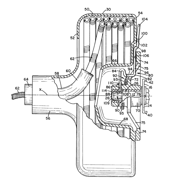
AB shown in FIGURE 3, the drum C ha~ sn sxis X sbout
which it rotstes, snd is compri~ed of an sxial extending
cylindricsl outer wall 50 snd r~dislly inward extending
front snd bsck end wa~ls 52 snd 54, respective}y. The front
end wall S2 terminstes in sn sxislly outward extendinR
cylindricsl throat section 56 within which an 8xi811y
extendin~ cable guide tube 58 is supported. The guide tube
58 is formed with a curved inner end 60 leading into the
hollow interior of the drum C and into which the convention-
81 drsin clesning cab}e 62 ~tored in coiled co~dition in the
drum i~ fed. Cuide tube 58 terminates st its outer end in a
nozzle end 64 out of which the csble 62 i~ fed into the
drain pipe to be cleaned.
The b~ck end w8~1 54 of the drum C i~ formed with sr
generally sxislly inwardly extending ann~lar wsll portion 66
formi~g 8 centrally located outwardly opening receo~ or wel~
opening 68 therein within which a cylindrical hub or sxle
housing portian 70 of the drum is mounted in a position
extending axially thereof. The hub portion 70 is provided
with a generally radially outward extending and axislly
offset mounting flsnge 72 which extends slongside the back
end wall 54 of the drum C for a short distance snd i8 bolted
thereto ~round its rim 74 to secure the hub portion 70 in
plsce on the drum C in sxially centered position thereon
within the well opening 68. The offeet portion of the
20~X~7~
RT-7937
fl~nge 72 is provided with a plurality of apertures 75
~psced apsrt therearound for weight reducin~ purposes.
The hub portion 70 is provided interiorly thereof with a
cylindrical inner bearing 76 axislly sligned with the drum
axis X for journsling the drum C for rotation about its axis
on the chassis mounted axle 26 of the machine A.
In accordance with the invention, the drum C i8 provid-
ed with integral retainer mechanism 80 for releassbly
mounting the drum on the axle 26 for rotation thereon while
affording quick and easy disassembly therefrom when de~ired,
as for replacement of the drum with a like drum provided
with a different diameter csble 62 or for addin~ an addi-
tional length of cable to a cable already inserted in 8
drain pipe or sewer. The retainer mechanism 80 comprises an
elongated retainer latch member 82 preferably in the form of
a metal rod or bar which extends in a plsne rsdiall~ of the
hub portion 70 and i8 provided with an inner end portion 84
which is slidable within a radislly extending passagewsy 86
in the hub portion. The lstch member 82 is biased inwardly
of the hub portion 70 to en~aRe at its inner end 88 within
an annular groove 90 in the chassis mounted axle 26 to lock
the drum C in place thereon against sxial movement relative
thereto.
The latch member 82 is biased radially inwsrdly of the
hub portion 70 by suitable biasing member 92 which may
comprise a tension or extension coil spring 93 connected at
its opposite ends to an axially extending and radially
inwardly offset crook portion 94 of the latch member and
looped around the hub portion 70 in a tensioned condition.
Alternatively, the biasing member 92 may comprise instead a
gàrter spring or an elastic band or 0-ring stretched and
looped around the offset bent crook portion 94 of the lstch
member 82 and around the hub portion 70 of tbe drum. The
~nwardly offset crook portion 94 of the latch member 82
projects into and is accommodated within one of the weight
x~
RT-7937
reducing apertures 75 formed in and 6psced ~psrt sround the
offset web portion of the flange 72.
The outer end portion 96 of tbe lstch member 82 extendfi
rsdi~lly outwsrd of the hub portion 70, between the bolting
rim 74 of the f}s~ge 72 on the hub portion 70 snd the back
end wsll 54 of the drum C, through 8 ~rooved reces~ 98
formed in the bsck end wall 54 providing 8 confining guide
chsnnelway for the outer end portion 96 of the latch member
82. Outwardly beyond the rim 74 of the flsnge 72, the outer
end portion 96 of the lstch member 82 is offset sxislly
outward from the bsck end wall 54 of the drum C to form sn
off~et end portion 100 extending to the outside of the drum
clo6ely slong~ide and in engagement with the back end wall
54 of the drum, as indicated at 102. The offset end portion
100 of the latch member 82 terminates in a suitable hand
hold or grip such a8 a ring-~haped portion 104 for enabling
the manual grasping and radially outward pulling of the
radially inward bissed lstch member 82 a sufficient distance
to disengage its inner end 88 from within the annular groove
90 in the axle 26 80 8B to free the drum C for ea~y sxial
removal therefrom. As shown in FIGURE 3, tbe hand grip 104
of the latch member 82 i6 bent at 8 Bl ight sngle outwardly
away from the back end wall 54 of the drum C in order to
provide clearance for enabling the manual grasping of the
hand grip 104. The engagement of the outer end portion 96
of the latch member 82 in groove 98 and with the inside face
106 of the rim 74 of the hub flange 72 provides a guideway
for the latch member 82 which, in cosction with the guidin~
of the inner end 88 of the latch member in the lstch pas-
sageway 86 in the hub portion 70 of the drum C, ~ssures the
true radial outwardly release movement of the retsiner latch
me~ber 82, when manually pulled outwardly to relesse the
drum C from its locked position on the chassis axle 26. This
prevent~ the binding of the latch member in the lstch
ps~agewsy 86.
- `:
O~liX~71
RT-7937
The inner end extremity of the inner end portion 84 of
the retainer latch member 82 iB beveled 88 indicated at 108
in a direction for camming engsgement with the end 109 of
the axle 26, when the drum C is axislly moved onto the axle,
to thereby displace the retainer latch member 82 rsdially
outwsrd to permit the unre~tricted axisl movement of the
drum C into it6 latched position on the axle 26. Also, the
inner end portion 84 of the latch member 82 i8 provided with
a suitsble ~top ~uch 8S a pair of dismetrically opposite
upset projections 110 thereon for en8sging with the outer
6ide of the hub portion 70 to lim~t the rsdisl inward biased
movement of the latch member into the hub portion to a
position in which only the beveled inner end extremity 108
of the latch member pro~ects into the axle receiving bearing
opening 112 of the hub portion 80 as to assure the csmming
engagement of the beveled inner end extremity with the end
of the axle 26 during the axial movement of the drum C
thereonto. To facilitate the camming action of the beveled
inner end extremity 108 to displace the retainer latch
member 82 radially outward during the axial movement of the
drum C onto the axle 26 to rotatively mount it in place
thereon, the end 109 of the sxle 26 i~ also beveled as
indicated at 114 in order to al~o have camming engagement
with the beveled inner end extremity 108 of the retainer
latch member 82.
During the axial movement of the hub portion 70 of the
drum C onto the axle 26 of the machine frame or chassis B to
rotatively mount the drum in place thereon, the retainer
latch 82 is radially retracted out of the axle bearing
opening 112, by the camming interengagement of the beveled
camming surfaces 108 and 114 on the lstch 82 and axle 26, to
permit the movement of the drum hub portion 70 to its fully
inserted position on the axle 26 at which time the biased
retainer latch 82 then snap-lock~ into the annular groove 90
on the axle to lock the drum C in place thereon. The drum
~2X7~
RT-7937
may be quic~ly and ea6ily dis~ssembled from the mschine
frame or c~a6si6 B, a8 for replscement by snother drum,
simply by msnuslly pulling the biased retsiner lstch 82
rsdislly outwsrdly of the drum a sufficient di6tsnce to
disengsge the inner end 88 of the lstch from its locking
engagement within the annulsr groove 90 in -the axle 26,
thereby freeing the drum for sxisl removsl from the sxle.
From the sbove description, it will be sppsrent that
the present invention provides a drsin clesner mschine of
novel construction in which the axle on which the rotsry
drum rotstes is mounted on the machine frsme or chsssis
in~tesd of on the drum as ha6 been cu6tomary heretofore,
thereby reducing the weight of the normslly cumbersome drum
with its stored drain clesning csble snd thereby rendering
it essier to hsndle both when assembling it with, or when
dissssembling it from the chsssis a8 for replscing it with
another drum contsining a different dismeter csble. More-
over, the provigion in sccordance with the invention of the
releasable retsiner mechsnism 80 for locking the drum C in
place on the sxle 26 enables the quick snd easy sssembly of
the drum C in rotstive mounted position on the chassis of
the mschine a8 well a8 its dissssembly therefrom 88 for
cleaning snd repair purposes or for replscing it with
another drum with a different diameter csble or to sdd an
sdditional length of cable to a csble slready inserted in a
drsin, where the job requires a grester length of cable.
The invention hs6 been described with reference to the
preferred embodiment. Obviously modificstions and alters-
tions will occur to others upon the resding and understsnd-
ing of this specification snd it is my intention to include
all 6uch modificstions and slterstions insofar as they come
within the scope of the appended clsims.
-- 10 -