Sélection de la langue

Search

Sommaire du brevet 2005130 

Énoncé de désistement de responsabilité concernant l'information provenant de tiers

Une partie des informations de ce site Web a été fournie par des sources externes. Le gouvernement du Canada n'assume aucune responsabilité concernant la précision, l'actualité ou la fiabilité des informations fournies par les sources externes. Les utilisateurs qui désirent employer cette information devraient consulter directement la source des informations. Le contenu fourni par les sources externes n'est pas assujetti aux exigences sur les langues officielles, la protection des renseignements personnels et l'accessibilité.

Disponibilité de l'Abrégé et des Revendications

L'apparition de différences dans le texte et l'image des Revendications et de l'Abrégé dépend du moment auquel le document est publié. Les textes des Revendications et de l'Abrégé sont affichés :

  • lorsque la demande peut être examinée par le public;
  • lorsque le brevet est émis (délivrance).
(12) Brevet: (11) CA 2005130
(54) Titre français: RECTIFIEUSE DE DENTS DE SCIES
(54) Titre anglais: SAW BLADE TOOTH GRINDER FOR SAWS
Statut: Réputé périmé
Données bibliographiques
(52) Classification canadienne des brevets (CCB):
  • 51/47
(51) Classification internationale des brevets (CIB):
  • B23D 63/14 (2006.01)
  • B23D 63/00 (2006.01)
  • B23D 63/12 (2006.01)
(72) Inventeurs :
  • WILLIAMS, CHRISTOPHER CONRAD (Canada)
(73) Titulaires :
  • WILLIAMS & WHITE MACHINE SHOP (Canada)
(71) Demandeurs :
  • WILLIAMS, CHRISTOPHER CONRAD (Canada)
(74) Agent: FETHERSTONHAUGH & CO.
(74) Co-agent:
(45) Délivré: 1995-06-13
(22) Date de dépôt: 1989-11-16
(41) Mise à la disponibilité du public: 1991-05-16
Requête d'examen: 1991-11-07
Licence disponible: S.O.
(25) Langue des documents déposés: Anglais

Traité de coopération en matière de brevets (PCT): Non

(30) Données de priorité de la demande: S.O.

Abrégés

Abrégé anglais


A device for grinding saw blades, both band saws and
circular saws so that a predetermined tooth profile is
obtained utilizes a grinding head that moves in one plane and
moves the saw in a second plane. The device comprises a saw
blade mount, an indexing system for indexing a saw tooth to
move in a first plane, a grinding head to grind a saw tooth,
a grinding head travel arrangement to move the grinding head
in a second plane, the second plane being at an angle of
about 35° from the perpendicular of the first plane, and a
control system for controlling movement of the saw blade in
the first plane and the grinding head in the second plane to
ensure a predetermined saw tooth profile is ground.

Revendications

Note : Les revendications sont présentées dans la langue officielle dans laquelle elles ont été soumises.


The embodiments of the present invention in which an
exclusive property or privilege is claimed are defined as
follows:


1. An apparatus for grinding saw teeth on a saw blade,
comprising;


saw blade mounting means,


saw blade indexing means for indexing a saw tooth to
move in a first plane on the mounting means, the saw blade
indexing means operated by a first servo motor,


a grinding head having means to grind a saw tooth,


grinding head travel means to move the grinding head in
a second plane, the second plane being at an angle of about
35° from the perpendicular of the first plane, the grinding
head travel means operated by a second servo motor, and


control means, wherein said servo motors are
simultaneously activated by a programmed computer, for
controlling movement of the saw blade in the first plane,
and at the same time controlling movement of the grinding
head in the second plane such that the blade and the


- 9 -

grinding head are moved simultaneously during grinding of a
curved portion of the saw tooth to ensure a predetermined
curved saw tooth profile is ground.


2. The apparatus according to Claim 1 wherein the saw blade
indexing means indexes each saw tooth to complete grinding a
saw blade.


3. The apparatus according to Claim 1 wherein the grinding
means comprises a rotating disk, with abrasive on the
periphery, to grind across the face of the saw tooth.


4. The apparatus according to Claim 1 wherein the grinding
means comprises a small cylindrical shaped grinder wheel to
fit within the profile of the saw tooth and grind in line
with the face of the saw tooth.


5. The apparatus according to Claim 1 wherein the mounting
means comprises a saw support having an adjustment means for
accommodating different sizes of saw blades, and clamp means
to clamp the saw blade but permit movement from the indexing
means.


6. The apparatus according to Claim 1 wherein the indexing
means comprises an arm with saw tooth engaging means,
wherein the arm pivots to lift the saw tooth engaging means


- 10 -

when moving away from the grinding head to engage the
adjacent saw tooth, and means to move the arm away from and
towards the grinding head in the first plane.


7. The apparatus according to Claim 1 wherein the servo motors
drive screw threads connected to the indexing means and
grinding head.


8. An apparatus for grinding saw teeth on a saw blade,
comprising:


saw blade mounting means,


saw blade indexing means for indexing a saw tooth to
move in a first plane on the mounting means, the saw blade
indexing means operated by a first servo motor,


a grinding head having means to grind a saw tooth,


grinding head travel means to move the grinding head in
a second plane, the second plane being at an angle of about

35° from the perpendicular of the first plane, the grinding
head travel means operated by a second servo motor,


control means, wherein said servo motors are
simultaneously actuated by a programmed computer, for

- 11 -

controlling movement of the saw blade in the first plane and
at the same time controlling movement of the grinding head
in the second plane such that the blade and the grinding
head are moved simultaneously during grinding of a curved
portion of the saw tooth to ensure a predetermined saw tooth
profile is ground; wherein the first servo motor drives a
first screw thread connected to the indexing means and the
second servo motor drives a second screw thread connected to
the grinding head.


- 12 -

Description

Note : Les descriptions sont présentées dans la langue officielle dans laquelle elles ont été soumises.

Z0051;~0

44494-7
l ~ Canada


SAW BLADE TOOTH GRINDER FOR SAWS


The present invention relates to a device for grinding
saw blade teeth on band or circular saws and more
specifically to a saw blade tooth grinder wherein a
predetermined tooth profile may be ground.


Band saw blades and circular saw blades used in saw
mills and the like are sharpened from time to time and this
is done by a grinder. Machines are available wherein a saw
blade is held for sharpening each tooth. A grinder is used
for this purpose and there are presently available devices
wherein the grinder follows a profile using a mechanical cam
arrangement to ensure that each tooth is cut to a
predetermined profile. The cam arrangement requires
considerable set up time for different saw blades which is
time consuming and requires constant supervision.


It is an aim of the present invention to provide an
apparatus for grinding saw teeth on a saw blade wherein the

grinding of each individual saw tooth is accomplished by
means of servo motors that combine to push the saw blade in
the plane of the saw and at the same time move a rotating
grinder down in another plane to grind each saw tooth in
accordance with a predetermined profile. The profile is

~*
",

2005130

determined by utilizing a computer program or the like and
thus it is simply a matter of reprogramming a computer rather
than disassembling and reassembling a complicated mechanical
machine. Furthermore, once the saw blade has been mounted on
the apparatus and the guiding commenced. The machine grinds
each tooth unattended, and then stops after the last tooth is
ground.


The present invention provides an apparatus for grinding
saw teeth on a saw blade comprising saw blade mounting means,
saw blade indexing means for indexing a saw tooth to move in
a first plane on the mounting means, grinding head having
means to grind a saw tooth, grinding head travel means to
move the grinding head in a second plane, the second plane
being at an angle of about 35 from the perpendicular of the
first plane, and control means for controlling movement of
the saw blade in the first plane and the grinding head in the
second plane to ensure a predetermined saw tooth profile is
ground.


In drawings which illustrate embodiments of the
invention,


Figure 1 is a front elevational view showing one
embodiment of a saw tooth grinder according to the present

invention.


-- 2

2005130
-


Figure 2 is a side view of the apparatus shown in
Figure 1.

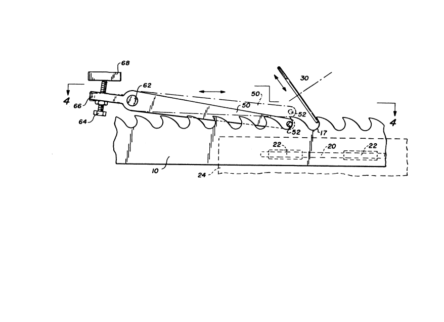
Figure 3 is a detailed front view of the saw blade
indexing means and grinding wheel of Figure 1.

Figure 4 is a detailed top view taken at line 4-4
of Figure 3.

Figure 5 is a side view showing another embodiment
of a saw tooth grinder according to the present application.

Figure 6 is a detailed front view of a grinding
wheel grinding across a saw tooth.

Figure 7 is a detailed plan view of a saw blade
showing the grinding marks across the face of the saw blade.

Figure 8 is a detailed front view of a small
cylindrical slated grinding wheel grinding in line with a saw
tooth.

Figure 9 is a detailed plan view of a saw blade
showing the grinding marks in line with the face of the saw
blade.

One embodiment of the grinding machine is illustrated in
Figures 1 and 2 wherein a band saw blade 10 rests on a

2()05130

support 12 at one side of a frame 14 sitting in a tray
resting on base 16. The saw teeth 17 are at the top held for
grinding. The saw support 12 for the saw blade 10 can be
adjusted up and down by a manually operated slide to take
into account different thicknesses of band saw blades. The
slide has a hexagonal head 18 for attaching a handle or
wrench.

The saw blade 10 is held in position by a carbide face
plate 20 in the frame 14 and two guide rollers 22 in a
pivoted mounting panel 24 with a pivot point 26 at the centre
joined to the frame 14 and an air cylinder 28 beneath the
pivot point 26 to push the top of the panel inwards so that
the blade 10 is held between the guide rollers 22.

A grinding wheel 30 driven by a constant speed motor 32
is mounted with its axis at an angle of substantially 35 to
the horizontal or to the plane of the saw blade 10. The
grinding wheel motor 32 is mounted on a guide grinding head
34 that moves up and down a straight track in a plane which
is perpendicular to the axis of the grinding wheel 30 and
motor 32. A servo motor 36 moves the grinding head 34 up and
down the track to position the grinding wheel 30 relative to
the saw blade 10. The grinding head 34 and track are mounted
on a set of manually adjusted slides supported on the frame
14. A vertical slide is adjusted by a wheel 42 for raising
and lowering the platform 34, a longitudinal slide is
adjusted by wheel 44 for moving the grinding head slide 34

2005130
_,
in line with the saw blade 10 and hexagonal head 46 to move
the grinding head 34 backwards and forwards from the saw
blade 10, to locate the grinding wheel in the centre of the
saw blade 10, and accommodate different thickness of saw
blade 10. The three slides permit the grinding wheel 30 to
be located in the required relationship to the saw blade 10.
The vertical slide and the longitudinal slide move the
grinding wheel 30 so that a cut may be taken on the saw blade
10 .


The saw blade itself is moved by an indexing mechanism
including an arm 50 with a saw tooth engaging pin 52 which
moves backwards and forwards on a screw thread powered by a
servo motor 54.


Figures 3 and 4 illustrate details of the indexing
mechanism wherein the arm 50 having a tooth engaging pin 52
at one end engages in one tooth 17 of the saw blade. The arm
50 has a pivot 62 and is weighted so that the pin 52 is
always pressing downwards. An adjustable set screw 64
through a tab 66 extending from the back of the arm 50 rests
against a flange 68 which forms part of the indexing
mechanism moved by the servo motor 54. The control system
for the unit is contained in the control cabinet 50 behind
the frame 14.


In operation the movement of the blade indexing means
and the grinding wheel 30 are controlled by the control

200S1~0

system which is a computer programmed to grind a
predetermined saw tooth profile. The servo motors 36 and 54
move the grinding wheel 30 downwards and then back up again
along the angular plane at the same time as the tooth
engaging pin 52 pushes the saw blade 10 forward in the
horizontal plane so that a tooth 17 one ahead of that engaged
by the pin 52 is ground. This can be seen in Figure 3. Once
the indexing system has pushed the tooth 17 to its furthest
forward position then it moves back and the pin 52 rides up
over the tooth 17 to drop into the next space behind the
tooth 17 and commences the grinding sequence for the next
tooth.


Whereas a band saw blade 10 is illustrated i the
drawings, a circular saw blade can also be ground on the
machine. The circular saw blade is mounted axially at axis
69, clamped in substantially the same manner as the band saw
blade, and indexed by the indexing mechanism to rotate tooth
by tooth.


The computer is also programmed to count the number of
teeth ground so after the total number of teeth on the band
saw blade or the circular saw blade have been ground, then
the machine stops itself.


Variable teeth parameters may be ground by simply
feeding a new program into the computer which affects the
movement of the two servo motors driving the grinding wheel

ZC~OSl~O

30 and the pusher pin 52. The two servo motors 36 and 54
preferably drive screw threads with ball bearings for ease
and accuracy of movement. With the second plane being at an
angle of about 35, from the perpendicular of the first plane
the combination of movement of the saw blade 10 and the
grinding head 34, permits cutting angles from about 25 up to
35 from the perpendicular of the first plane, provided the
grinding wheel 30 does not foul the back of the adjacent saw
tooth 17.


Figure 5 illustrates another embodiment wherein the
grinding wheel 30 shown in Figure 1, which has a reasonably
large diameter and grinds across the face of a tooth 17, is
replaced by a small cylindrical shaped grinding wheel 72 that
rotates within the saw tooth 17 in line with the blade 10.
The cylindrical grinder 72 moves in the angular plane so that
it grinds the tooth profile 17 in the same way as the
grinding wheel 30 shown in Figure 1. Figures 6 and 7
illustrate the grinding wheel having an abrasive material on
the periphery of the wheel 30. The abrasive material may be
diamond grit or a cubic boron nitrite sold under the trade
mark BORAZON. As seen in Figure 7 the grinding lines occur
across the face of the saw tooth 17. Figure 8 shows the
cylindrical grinder 72 and as can be seen in Figure 9 the
grinding lines are in line with the saw blade 10. It has
been found that less stress is built up within the saw blade
10 if the grind lines are in line with the saw blade rather
than across the face.


20051;~0

`_

In one embodiment the grinding wheel 30 has an eight
inch diameter, one quarter inch wide, with a sixty mesh
diamond abrasive bonded in a nickel matrix. Full flood
cooling is provided for grinding and the frame 14 stands in a
tray for collection of the coolant.


In one embodiment the servo motor 54 is programmed to
move the saw tooth forward in one and a half seconds and a
half second return to index the next tooth. The accuracy
with utilizing computer control is to within one thousandth
of an inch or less. For the case of the cylindrical grinder
72 a half inch diameter cylindrical grinder 72 has proven
satisfactory. Safety controls are provided to turn off the
machine due to overloading. Covers are provided over the
grinding wheel 30 or cylindrical grinder 72 for safety.


Various changes may be made to the embodiments shown
herein without departing from the scope of the present
invention which is limited only by the following claims.

Dessin représentatif
Une figure unique qui représente un dessin illustrant l'invention.
États administratifs

Pour une meilleure compréhension de l'état de la demande ou brevet qui figure sur cette page, la rubrique Mise en garde , et les descriptions de Brevet , États administratifs , Taxes périodiques et Historique des paiements devraient être consultées.

États administratifs

Titre Date
Date de délivrance prévu 1995-06-13
(22) Dépôt 1989-11-16
(41) Mise à la disponibilité du public 1991-05-16
Requête d'examen 1991-11-07
(45) Délivré 1995-06-13
Réputé périmé 2004-11-16

Historique d'abandonnement

Il n'y a pas d'historique d'abandonnement

Historique des paiements

Type de taxes Anniversaire Échéance Montant payé Date payée
Le dépôt d'une demande de brevet 0,00 $ 1989-11-16
Enregistrement de documents 0,00 $ 1990-05-04
Rétablissement: taxe de maintien en état non-payées pour la demande 200,00 $ 1992-01-07
Taxe de maintien en état - Demande - nouvelle loi 2 1991-11-18 50,00 $ 1992-01-07
Taxe de maintien en état - Demande - nouvelle loi 3 1992-11-16 50,00 $ 1992-09-29
Taxe de maintien en état - Demande - nouvelle loi 4 1993-11-16 50,00 $ 1993-10-14
Taxe de maintien en état - Demande - nouvelle loi 5 1994-11-16 75,00 $ 1994-10-12
Taxe de maintien en état - brevet - nouvelle loi 6 1995-11-16 75,00 $ 1995-11-09
Taxe de maintien en état - brevet - nouvelle loi 7 1996-11-18 75,00 $ 1996-10-02
Taxe de maintien en état - brevet - nouvelle loi 8 1997-11-17 75,00 $ 1997-11-04
Taxe de maintien en état - brevet - nouvelle loi 9 1998-11-16 275,00 $ 1999-01-27
Taxe de maintien en état - brevet - nouvelle loi 10 1999-11-16 100,00 $ 1999-11-09
Taxe de maintien en état - brevet - nouvelle loi 11 2000-11-16 100,00 $ 2000-09-20
Taxe de maintien en état - brevet - nouvelle loi 12 2001-11-16 100,00 $ 2001-11-15
Taxe de maintien en état - brevet - nouvelle loi 13 2002-11-18 200,00 $ 2002-11-05
Titulaires au dossier

Les titulaires actuels et antérieures au dossier sont affichés en ordre alphabétique.

Titulaires actuels au dossier
WILLIAMS & WHITE MACHINE SHOP
Titulaires antérieures au dossier
WILLIAMS, CHRISTOPHER CONRAD
Les propriétaires antérieurs qui ne figurent pas dans la liste des « Propriétaires au dossier » apparaîtront dans d'autres documents au dossier.
Documents

Pour visionner les fichiers sélectionnés, entrer le code reCAPTCHA :


Pour visualiser une image, cliquer sur un lien dans la colonne description du document. Pour télécharger l'image (les images), cliquer l'une ou plusieurs cases à cocher dans la première colonne et ensuite cliquer sur le bouton "Télécharger sélection en format PDF (archive Zip)" ou le bouton "Télécharger sélection (en un fichier PDF fusionné)".

Liste des documents de brevet publiés et non publiés sur la BDBC .

Si vous avez des difficultés à accéder au contenu, veuillez communiquer avec le Centre de services à la clientèle au 1-866-997-1936, ou envoyer un courriel au Centre de service à la clientèle de l'OPIC.


Description du
Document 
Date
(yyyy-mm-dd) 
Nombre de pages   Taille de l'image (Ko) 
Dessins représentatifs 1999-07-12 1 13
Page couverture 1995-06-13 1 15
Abrégé 1995-06-13 1 20
Abrégé 1995-06-13 1 19
Description 1995-06-13 8 252
Revendications 1995-06-13 4 91
Dessins 1995-06-13 3 63
Taxes 2001-11-15 1 39
Taxes 1999-01-27 2 76
Correspondance 2001-11-15 1 22
Taxes 2002-11-05 1 39
Taxes 2000-09-20 2 70
Demande d'examen 1994-11-02 2 69
Correspondance de la poursuite 1994-11-16 2 64
Correspondance reliée au PCT 1995-04-04 1 33
Lettre du bureau 1992-03-26 1 35
Correspondance de la poursuite 1991-11-07 1 24
Taxes 1996-10-02 1 45
Taxes 1995-11-09 1 33
Taxes 1994-10-12 1 37
Taxes 1993-10-14 1 28
Taxes 1992-09-29 1 28
Taxes 1992-01-07 1 31
Correspondance 1992-03-05 1 24