Note : Les descriptions sont présentées dans la langue officielle dans laquelle elles ont été soumises.
ZQOS43;~
(44 965 a) A ROTARY DRUM FILTER
____________________
BACKGROUND OF THE INVENTION
___________________________
FIELD OF THE INVENTION
The present invention relates to a rotary drum
filter having a drum which is rotatable around a substant-
ially horizontal axis and having a filter cake cleaning-
off unit, which drum and which cleaning-off unit-are
located inside of a filter housing that includes a raw
air inlet, a clean air outlet and a filter cake discharge
section, whereby the raw air inlet faces the outer jacket
surface of the drum and the clean air outlet faces the
inner jacket surface of the drum.
DESCRIPTION OF THE PRIOR ART
____________________________
Such a rotary drum filter is generally known, and
its filter cake cleaning-off unit operates with pressurized
air in order to detach or remove, respectively, the filter
20(3 5~3~
cake from the outer jacket surface of the drum. Accordingly,
the jet of pressurized air is directed in the mentioned
rotary drum filter design from within the drum towards the
inner jacket surface of the drum, flows therethrough and
throws the filter cake located on the outer jacket surface
of the drum off towards the outside. Known rotary drum
filters of the above mentioned design incorporate the
drawback that due to the impact of the pressurized air
the filter removed from the drum does not fall downwards
in a compact state, but rather dust thereof is raised,
which again reaches the outer jacket surface of the drum.
Accordingly, the air-flows within the housing of the filter
are responsible for such happening, which air-flows pre-
vent a compact setting of the dust in a settling space
(bin, container, trough) for such dust.
SUMMARY OF THE INVENTION
Hence, a general object of the invention is to
provide a rotary drum filter by means of which the above
mentioned drawback may be avoided, such that accordingly
it is possible to avoid the dust, having been cleaned off
by the cleaning-off unit, from reaching anew the outer
jacket surface of the drum.
A further object of the present invention is to
i~Q0~3Z
provide a rotary drum filter having a filter housing which
comprises a vertically upper filter zone and a filter cake
settling zone located below the filter zone such that the
filter housing is partitioned into two zones, whereby a
part of the partitioning plane is formed as cleaning-off
zone and the rest of the partitioning plane is formed
substantially air-tight.
BRIEF DESCRIPTION OF THE DRAWING
The present invention will be better understood
and objects other than those set forth above will become
apparent when consideration is given to the following
detailed description thereof. Such description makes
reference to the annexed drawing, wherein :
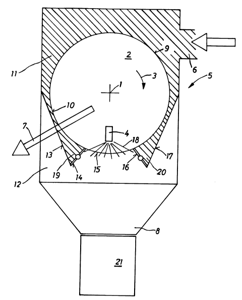
Fig. 1 illustrates a schematic front view of the
horizontally lying drum of a rotary drum filter structured
in accordance with the present invention; and
Fig. 2 illustrates schematically a detail of the
lower part of the rotary drum filter of Fig. 1.
DESCRIPTION OF THE PREFERRED EMBODIMENT
The rotary drum filter includes a drum 2 which is
rotatable around an axis 1. It shall be assumed that the
drum 2 is able to rotate intermittently in the direction
;~0`{3 ~43%
of an arrow 3 in this embodiment. A filter cake cleaning-
off unit is located at the inside of the drum 2. The drum
2 and the filter cake cleaning-off unit 4 are located with-
in a filter housing 5, which includes a raw air inlet 6,
a clean air outlet 7 and a filter cake discharge 8, where-
by the raw air inlet 6 faces the outer jacket surface 9 of
the drum 2. The clean air outlet 7 faces the inner jacket
surface 10 of the drum, such that accordingly the clean air
is discharged coaxially out of the inner area of the drum
2.
The filter housing 5 is partitioned vertically
into an upper filter zone 11 and a filter cake settling
zone 12 located thereunder, and whereby for better under-
standing the upper filter zone 11 is identified in Fig. 1
by a hatching. A partition plane or section, respectively,
is located between the two zones 11 and 12 and consists
of members 13 to 17. The member 15 of the partition plane
is formed as cleaning-off sector and accordingly when
cleaning the filter cake off,the jet 18 of pressurized air
is directed against this sector 15. The rest of the parti-
tion plane, ie members 13, 14, 16 and 17 include at least
one flap that can be opened and be closed such to allow
a selective opening and thus connecting of the filter
zone 11 to the filter cake settling zone 12. The two
surface or plane parts 14 and 16 of the partition plane
X~5432
of the illustrated example are shaped as flaps, which two
flaps 14 and 16 are illustrated more in detail in Fig. 2.
The partition surface 13 to 17 shall be designed as air-
tight as possible up to the cleaning sector 15 which means
that the two parts 13 and 17 are mounted in air-tight
manner at the upper end of the housing 5 and that, further-
more, the two flaps 14 and 16 are to abut at their two
flap ends as air-tight as possible onto the outer jacket
surface 9 of the drum 2 and at the other end at the
members 13 and 17, respectively, such that accordingly
the raw air must penetrate from the filter zone 11 through
the outer and the inner jacket surface 9, 10 of the drum
2.
Figures 1 and 2 disclose that the section 13
and the flap 14 of the partition plane form together a
pocket 19 of the filter zone 11, and it can be stated
that the flap 14 is located at the bottom of this pocket
19. In a similar manner the section 17 and the flap
16 of the partition plane form a second pocket 20. The
two pockets 19 and 20 are located together with their
flaps 14 and 16 at both sides of the cleaning-off zone 15
and immediately adjacent thereto. Each pocket 19, 20 of
the illustrated example has a V-shape, whereby one of the
legs of the V-shape of the pocket 19 is formed by the
flap 14 and the other leg of the V-shape is formed by the
20~5Æ32
section 13 of the partition plane. The pocket 20 has also
a V-shape, whereby the one leg of the V-shape is formed
by the flap 16 and the other leg of the V-shape is formed
by the section 17 of the partition plane. Both sections
13 and 17 are designed as chute such that dust deposited
thereon can glide downwards into the pockets 19 and 20.
The filter cake discharge 8 of the housing 5 includes
also obliquely extending walls, and has accordingly also
the shape of a hopper, such that the filter cake falling
downwards or dust that has been detached from the filter
cake may fall into a settling space located thereunder,
which in the illustrated example is designed as a bucket
21.
The design of the two flaps 14 and 16 and their
operation for an opening or closing, respectively,there-
of is illustrated in detail',in Fig. 2. The position of the
two flaps 14 and 16 illustrated in solid lines represent
the closed state of the two flaps 14 and 16, in which
state they abut at their lower ends 22 and 23, respecti-
vely, sealingly the housing parts 24 and 25, respectively.
These housing parts 24 and 25 follow in turn sealingly
the two mentioned sections 13 and 17 of the partition
plane. The flap 14 carries at its end facing the drum 2 a
brush 26 intended to abut in an elastic manner the outer
jacket surface 9 of the drum 2. The flap 16 carries a
XQO~432
brush 27 in the same fashion. Accordingly, the brushes
26 and 27 define or limit, respectively,the cleaning off
zone 15 and contact sealingly the filter material 28 of the
drum 2, whereby only a small section of this filter mate-
rial 28 is illustrated in Fig. 2. The opened state of the
two flaps identified by 14' and 16' are illustrated by
broken lines.
The two flaps 14 and 16 are interconnected by a
linkage 29 allowing a simultaneous opening or closing of
both flaps 14, 16. The linkage 29 includes an abutment 30
for an operating cam 31 of the drum 2 for an opening of
the two flaps 14 and 16 against the force of a spring 32.
The two flaps 14 and 16, the linkage 29, the spring 32 and
the abutment 30 are assembled in a drum filter-insert 33
having the outer contour 33' that is part of the filter
cake settling zone 12 and which can be inserted into the
rest of the filter housing or be removed therefrom,
respectively.
The flap 14 is rigidly connected to an arm 34
supporting the abutment 30 and to a further arm 35. These
three structural members 14, 34 and 35 are pivotable
around a pivot pin 36 inserted rigidly in the insert 33.
The flap 16 is rigidly connected to an arm 37 and to a
further arm 38, whereby the structural members 16, 37 and
38 can be pivoted around a pivot pin 39 which is again
ZQ~5432
rigidly inserted or seated, respectively, in the insert
33. The two arms 35 and 38 are hingedly interconnected
by means of a coupling bar 40. The spring 32 is pivotably
mounted on the one end to the arm 37 and on the other end
to the arm 35. The two flaps 14 and 16 are held by means
of this tension spring 32 in their closed position. During
the intermittent rotation of the drum 2, the operation
cam 31 comes to contact the abutment 30 and pivots the
arm 34 into the position 34' illustrated with dash-dotted
lines. This follows in a movement of the two flaps 14 and
16 into their opened position 14' and 16'. After the
operation cam 31 has left the abutment 30, the spring 32
pulls the two flaps 14 and 16 again into their closed
position. In this position of the flaps 14, 16 a filtering
of the raw air takes place.
In order to clean the filter cake off, the
pressurized air jet 18 is directed from the jet nozzle
4 against the cleaning-off section 15, whereupon the
filter cake which is then detached falls downwards into
the bucket 21. Thereafter, the drum 2 is rotated inter-
mittently by the angle of circumference of the cleaning-
off zone 15 further in the direction of the arrow 3,
whereby the operation cam 31 opens both flaps 14 and 16.
Thus, filtered dust located in the filter zone 11 and
specifically in the two pockets 19 and 20 is led down-
;~Q~5~3;~:
wards into the bucket 21, during which this filter dustslides downwards along the two sections 13 and 17 acting
as chutes. Accordingly, the pockets 19 and 20 have been
emptied. Upon a slight further rotation of the drum 2,
the two flaps 14 and 16 are again closed, and the filtering
of the raw air is begun anew. It is possible to open and
thereafter close the two flaps 14 and 16 once or several
times during a short time per full rotation of the drum 2.
The intermittent further rotation of the drum 2 can occur
eg every few minutes.
While there is shown and described a present
preferred embodiment of the invention, it is to be distinc-
tly understood that the invention is not limited thereto,
but may be otherwise variously embodied and practiced
within the scope of the following claims.