Sélection de la langue

Search

Sommaire du brevet 2005456 

Énoncé de désistement de responsabilité concernant l'information provenant de tiers

Une partie des informations de ce site Web a été fournie par des sources externes. Le gouvernement du Canada n'assume aucune responsabilité concernant la précision, l'actualité ou la fiabilité des informations fournies par les sources externes. Les utilisateurs qui désirent employer cette information devraient consulter directement la source des informations. Le contenu fourni par les sources externes n'est pas assujetti aux exigences sur les langues officielles, la protection des renseignements personnels et l'accessibilité.

Disponibilité de l'Abrégé et des Revendications

L'apparition de différences dans le texte et l'image des Revendications et de l'Abrégé dépend du moment auquel le document est publié. Les textes des Revendications et de l'Abrégé sont affichés :

  • lorsque la demande peut être examinée par le public;
  • lorsque le brevet est émis (délivrance).
(12) Brevet: (11) CA 2005456
(54) Titre français: AIGUILLE POUR MACHINE DE TUFTING
(54) Titre anglais: NEEDLE FOR USE IN TUFTING MACHINE
Statut: Réputé périmé
Données bibliographiques
(52) Classification canadienne des brevets (CCB):
  • 112/41
(51) Classification internationale des brevets (CIB):
  • D05B 85/00 (2006.01)
  • D05C 15/20 (2006.01)
(72) Inventeurs :
  • HAKUI, TAMOTSU (Japon)
(73) Titulaires :
  • HAKUI, TAMOTSU (Japon)
  • ASAHI TRADING CO., LTD. (Japon)
(71) Demandeurs :
(74) Agent: FETHERSTONHAUGH & CO.
(74) Co-agent:
(45) Délivré: 1999-08-24
(22) Date de dépôt: 1989-12-13
(41) Mise à la disponibilité du public: 1990-06-20
Requête d'examen: 1994-03-16
Licence disponible: S.O.
(25) Langue des documents déposés: Anglais

Traité de coopération en matière de brevets (PCT): Non

(30) Données de priorité de la demande:
Numéro de la demande Pays / territoire Date
63-165253 Japon 1988-12-20

Abrégés

Abrégé anglais


A needle for a tufting machine having its bottom end
pointed and having its lower half portion flattened. The
flattened portion has one edge thereof chamferred to form a
tapered face. A yarn insert hole is formed above the
pointed tip. It is inclined at a predetermined angle so
that its lowermost point will be located nearer to the
tapered edge than the other edge. The inclined hole allows
the looper to hook the yarn more reliably and helps to
decrease the possibility of cutting or mishooking of the
yarn.

Revendications

Note : Les revendications sont présentées dans la langue officielle dans laquelle elles ont été soumises.


The embodiments of the invention in which an exclusive
property or privilege is claimed are defined as follows.

1. A needle for a tufting machine having a pointed bottom
end and having the lower half portion thereof flattened,
said flattened portion having a first edge at one side
thereof chamfered to form a tapered edge and a second edge
at the other side, said needle being formed with a yarn
insert hole above said pointed bottom end, characterised in
that said yarn insert hole is inclined at a predetermined
angle so that its highest point will be located nearer to
said second edge than to said first edge.


6

Description

Note : Les descriptions sont présentées dans la langue officielle dans laquelle elles ont été soumises.


2005456
NEEDLE FOR USE IN TUFTING MACHINE
The present invention relates to a needle for use in a
tufting machine for manufacturing a tufted carpet.
As shown in Fig. 8, a tufting machine has a vertically
movable needle 42 for planting a pile yarn 43 through a web
of base cloth 41 being fed horizontally through the machine
and a looper 44 for hooking at its tapered tip the pile yarn
43 planted to form loops 45 on the underside of the base
cloth 41.
As shown in Fig. 9, a prior art needle for a tufting
machine has its bottom end pointed as at 46 and has a thin-
walled flat middle portion having one edge thereof chamfered
into a tapered face 47 to allow easy insertion of the
horizontally movable looper 44 between the yarn and the
needle 42. An oval yarn insert hole 48 is formed slightly
above the pointed tip 46 so that its major axis will
coincide with the axis 49 of the needle 42.
The looper 44 serves to catch the yarn planted through
the base cloth 41 to form loops.
In order to produce a patterned carpet by use of pile
yarns X, Y and Z different colors as shown in Fig. 10, it is
necessary to swing the needles of a tufting machine
laterally (in the direction of arrows A in Fig. 10).
But, if such a prior art needle is swung laterally e.g.
1


CA 02005456 1998-07-21
by five stitches at one stroke to form a large pattern on a
carpet, the pile yarn put through the needle 42 will be
pulled laterally, too, as shown in Figs. 11 and 12, and be
slanted. extremely at a portion between the top end of the
yarn insert hole 48 and the side of the looper 44 so that
the length a of the yarn at this portion will be too short
for the looper to hook the yarn reliably. This will
increase the possibility of cutting or mishooking of the
yarn, thus making it necessary to repair the pattern
afterwards.
It was therefore difficult to form a large and
beautiful pattern on a carpet with such prior art needles.
It is an object of the present invention to provide a
needle for a tufting machine which obviates the abovesaid
shortcomings and which can be moved sideways up to about a
five-stitch length at a stroke without the fear of cutting
or mish.ooking of the yarn.
In. accordance with the present invention there is
provided a needle for a tufting machine having a pointed
bottom end and having the lower half portion thereof
flattened, the flattened portion having a first edge at one
side thereof chamfered t:o form a tapered edge and a second
edge at the other side, the needle being formed with a yarn
insert hole above the bottom end, characterised in that the
yarn insert hole is inclined at a predetermined angle so
that its highest point will be
2


CA 02005456 1998-07-21
located nearer to the second edge than to the first edge.
Other features and objects of the present invention
will become apparent from the following description taken
with reference to the accompanying drawings, in which:
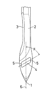
Figs. 1 to 3 are plan views of a portion of the needles
embodying the present invention;
Fi.g. 4 is a sectional view of the needle of Fig. 2;
Fi.g. 5 is a plan view of the same showing how it is
used;
Fi.g. 6 is a similar view of the same with the needle at
a higher position;
Fi.g. 7 is a side view of the same;
Fi.g. 8 is a view showing how a needle of a tufting
machine: operates;
Fi.g. 9 is a plan view of a prior art needle;
Fi.g. 10 is a bottom plan view of a carpet having a
pattern formed with the prior art needle;
Fi.g. 11 is a plan view of the prior art needle of Fig.
9 showing how it is used; and
Fi.g. 12 is a side view of the same.
Now referring to Figs. 1 to 6, the needle for a tufting
machine: according to the present invention has its
intermediate portion cut out at one side as shown at 2 to
form a thin-walled flat portion. An edge at one side of the
cut surface 2 is chamfered to form a tapered surface 3. The
3


2oos4ss
needle has a smoothly finished surface as a whole.
A yarn insert hole 4 is formed in the needle between
its tip 1 and the bottom end of the cut surface 2 so as to
extend obliquely at an angle o~ of 50 to 60 degrees (Fig. 1).
Its lowermost point is located nearer to the tapered edge 3
than the other edge.
The shape of the hole 4 may be parallelogrammatic (as
in Fig. 1), rectangular (as in Fig. 2), or oval (as in Fig.
3) .
The yarn insert hole 4 of the embodiment of Fig. 1 is
in the shape of a parallelogram having its four corners
rounded off and its short sides extending in parallel with
the axis 6 of the needle. Its peripheral surface is
finished up smoothly.
Now the operation of the needle for a tufting machine
according to the present invention will be described.
If the yarn 43 pulled by the needle is planted into the
base cloth after moving the needle sideways by about five
stitches at a stroke, it will engage the needle at the
uppermost point in the hole 4, i.e. the point farthest from
the axis 6 of the needle. In other words, the yarn 43 will
be inclined toward the edge 3, starting from a point apart
from the axis 6 of the needle by a distance b and thus, as
shown in Fig. 5, the length c of the portion of the yarn 43
in engagement with the side surface of the needle will be
4


2005456
longer than that on the prior art needle shown in Fig. 11.
This allows the looper to hook the yarn at its tip more
reliably.
The needle according to the present invention, which
can be moved by a longer distance sideways than any other
prior art needle without the fear of the cutting or mis-
hooking of the yarn, will make it possible to form a large
and luxurious-looking pattern on a carpet with a greater
number of yarns of different colors.
Also, less possibility of cutting or mishooking
increases the productivity and quality and less repair
decreases the manufacturing cost.

Dessin représentatif
Une figure unique qui représente un dessin illustrant l'invention.
États administratifs

Pour une meilleure compréhension de l'état de la demande ou brevet qui figure sur cette page, la rubrique Mise en garde , et les descriptions de Brevet , États administratifs , Taxes périodiques et Historique des paiements devraient être consultées.

États administratifs

Titre Date
Date de délivrance prévu 1999-08-24
(22) Dépôt 1989-12-13
(41) Mise à la disponibilité du public 1990-06-20
Requête d'examen 1994-03-16
(45) Délivré 1999-08-24
Réputé périmé 2004-12-13

Historique d'abandonnement

Il n'y a pas d'historique d'abandonnement

Historique des paiements

Type de taxes Anniversaire Échéance Montant payé Date payée
Le dépôt d'une demande de brevet 0,00 $ 1989-12-13
Enregistrement de documents 0,00 $ 1990-08-10
Taxe de maintien en état - Demande - nouvelle loi 2 1991-12-13 50,00 $ 1991-10-18
Taxe de maintien en état - Demande - nouvelle loi 3 1992-12-14 50,00 $ 1992-11-09
Taxe de maintien en état - Demande - nouvelle loi 4 1993-12-13 50,00 $ 1993-11-05
Requête d'examen 200,00 $ 1994-03-16
Taxe de maintien en état - Demande - nouvelle loi 5 1994-12-13 75,00 $ 1994-09-28
Taxe de maintien en état - Demande - nouvelle loi 6 1995-12-13 75,00 $ 1995-09-13
Taxe de maintien en état - Demande - nouvelle loi 7 1996-12-13 75,00 $ 1996-09-10
Taxe de maintien en état - Demande - nouvelle loi 8 1997-12-15 150,00 $ 1997-09-02
Taxe de maintien en état - Demande - nouvelle loi 9 1998-12-14 150,00 $ 1998-10-01
Taxe finale 300,00 $ 1999-05-12
Taxe de maintien en état - brevet - nouvelle loi 10 1999-12-13 200,00 $ 1999-10-12
Taxe de maintien en état - brevet - nouvelle loi 11 2000-12-13 200,00 $ 2000-09-21
Taxe de maintien en état - brevet - nouvelle loi 12 2001-12-13 200,00 $ 2001-08-23
Taxe de maintien en état - brevet - nouvelle loi 13 2002-12-13 200,00 $ 2002-10-29
Titulaires au dossier

Les titulaires actuels et antérieures au dossier sont affichés en ordre alphabétique.

Titulaires actuels au dossier
HAKUI, TAMOTSU
ASAHI TRADING CO., LTD.
Titulaires antérieures au dossier
S.O.
Les propriétaires antérieurs qui ne figurent pas dans la liste des « Propriétaires au dossier » apparaîtront dans d'autres documents au dossier.
Documents

Pour visionner les fichiers sélectionnés, entrer le code reCAPTCHA :


Pour visualiser une image, cliquer sur un lien dans la colonne description du document. Pour télécharger l'image (les images), cliquer l'une ou plusieurs cases à cocher dans la première colonne et ensuite cliquer sur le bouton "Télécharger sélection en format PDF (archive Zip)" ou le bouton "Télécharger sélection (en un fichier PDF fusionné)".

Liste des documents de brevet publiés et non publiés sur la BDBC .

Si vous avez des difficultés à accéder au contenu, veuillez communiquer avec le Centre de services à la clientèle au 1-866-997-1936, ou envoyer un courriel au Centre de service à la clientèle de l'OPIC.


Description du
Document 
Date
(yyyy-mm-dd) 
Nombre de pages   Taille de l'image (Ko) 
Dessins représentatifs 1999-08-16 1 3
Revendications 1994-03-02 1 14
Dessins 1994-03-02 3 63
Description 1994-03-02 5 130
Abrégé 1994-06-27 1 14
Abrégé 1994-03-02 1 14
Page couverture 1994-03-02 1 15
Description 1998-07-21 5 137
Page couverture 1999-08-16 1 25
Revendications 1998-07-21 1 17
Cession 1989-12-13 6 224
Poursuite-Amendment 1994-03-16 8 298
Correspondance 1990-03-15 3 86
Correspondance 1998-05-12 1 36
Poursuite-Amendment 1998-04-23 2 3
Poursuite-Amendment 1998-07-21 6 131
Taxes 1996-09-10 1 54
Taxes 1995-09-13 1 52
Taxes 1994-09-28 1 53
Taxes 1993-11-05 1 43
Taxes 1992-11-09 1 40
Taxes 1991-10-18 1 44