Note : Les descriptions sont présentées dans la langue officielle dans laquelle elles ont été soumises.
7~B
--1--
INV1140
STATIC PRESSURE DISPENSER OF WHIPPED PRODUCTS
AND PROCESS OF OPERATION
Field of the Invention
The present invention relates to the aeration of
whippable fluids and more particularly to a new and
improved apparatus and method for pressurized whipping or
emulsifying of food products and dispensing the same.
Description of the Prior Art
Whipped, aerated or emulsified ~ood products have
been ~nown and used for some time as well as methods and
apparatus for producing the same. Whipped cream, for
example for household and commercial use, was heretofore
produced by mechanical mixers and heaters that are manu-
ally or power driven. Currently, they have largely been
replaced by disposable aerosol cans and refillable pres-
sure whippers.
An important use of whipping equipment is to produce
whipped food products such as whipped cream, imitation
whipped cream and toppings for application to deserts
such as ice cream sundaes, cakes, pies and the like at
ice cream parlors, restaurants, hotels and commercial
bakeries wherein the toppings must remain stiff and
stable for relatively long periods of time and under
adverse conditions.
Whipping by effervescence, that is whipping by uti-
lizing pressurized equipment, is also well known, In
whipping by effervescence, a liquid food product such as
cream is introduced to a pressurized container and a gas
such as nitrous oxide alone or mixed with carbon dioxide
is dissolved or dispersed in the cream under pressure.
The solubilit~ o~ a gas in the cream is generally
directly proportional to the pressure encountered. Upon
release of the pressurized cream to the atmosphere
'' '' ,. . :''.
,~
.'. . ~ .
~ i'7'~
through a suitable nozzle, the gas passes out of solution
but the fat masses tend to remain as foam. Accordingl~,
whipped cream has been described as a dispersion of air
or gas cells and clumped fat masses as contiguous phases
in cream serums in the form of a more or less rigid foam.
The process of whipping includes dispensin~ and
incorporating small bubbles of a gas into a whippable
material to cause expansion of the material. The expan-
sion is commonly referred to as overrun. Thus, if the
whipped product occupies twice the space of the original
material, it is said to have one hundred percent overrun.
The stability of the whipped product, particularly under
high overrun, is in large measure dependent upon the size
of the gas bubbles and the uniformity in size and distri-
bution. The characteristics generally considered in
evaluating the quality of whipped products dispensed from
a pressurized container include its stiffness and stabil-
ity, over-run, drainage and appearance or shape. Such
qualities are in great part dependent upon the efficiency
of the pressurized whipping to provide intimate mixing of
the whippable liquid and the propellant or propellant
gas. Other qualities to be considered are the simplicity
of the process and apparatus for pressurized whipping and
dispensing of whipped products.
Exemplary of the state of the art of such pressurized
whipping apparatus and methods are the following U~S. ~2 ~/~f~ .
patents: ~ 5~ 5
1,899,236 2,375,833 3,713,841 ~ ~'~3
2,342,972 3,209,554 4,220,258 ` ~ J ,7
While such prior devices provide limited improvements 2~J/4-~t 4 $ q~
in the areas intended, there still exists a great need
for a new and improved static whipping method and an
apparatus which is simple in construction, efficient in
use and economical in manufacture. I have found that the
basic aeration theory, the e~uipment design and the pro-
cess of operating has some serious flaws. I have partic-
,
:.
~ . .
--3--
ularly found that an improvement can be made in the
introduction of the propellant gas into the whippable
liquid. I have found that there exists a need for a
whipping apparatus and method which is simple in con-
struction, efficient in use and economical in manufac-
ture. Previously, the gas was introduced into the whip-
pable liquid by manually agitating (shaking) the pressur-
ized container. I have found that when operators agitate
the whippable liquid, the quantity of gas introduced into
the cream can vary because the duration and degree of
agitation cannot be controlled and thus the amount of
overrun can vary widely. Moreover, if the container is
agitated too much, the liquid can turn into a ~el-like or
buttery consistency within the container and will be
expelled, if at all, in that gel-like or buttery consis-
tency which results in large amounts of cream waste in
the devices of the art. More importantly, the pressure
systems of the prior art cannot hold dissolved pressuriz-
ing gas in the cream for more than a limited amount of
time. When the gas emerges from the solution and returns
to the head space, the subsequent servings of cream
frequently become soft and semi-liguid and are unaccept-
able. The operator may attempt to rectify the problem by
shaking the container further or recharging the vessel
which causes the remaining cream to become buttery and
unusable.
Accordingly, a principal ob;ect of the present inven- `,
tion is to provide a whipping and dispensing device hav-
ing no need for agitation and method of whipping a whip-
pable liquid without agitation of the container that
holds the whippable liquid.
A further ob;ect of the present invention ls to pro-
vide a pressurized whipping and dispensing device which
provides for new and improved static whipping and dis-
pensing.
A still further ob;ect of the present invention is to
_4_ ~ 7~3
provide a static pressurized whipping and dispensing
device having improved cleaning, sanitation and mainte-
nance characteristics.
Another object of the invention is to provide static
whipping for portable dispensers in which the need for
shaking is eliminated thus improving safety since opera-
tors can avoid the risk of dropping the dispenser and
breaking it while it is being shaken.
These and other objects of the invention will in part
lo appear hereinafter and will in part become apparent after
consideration of the specification with reference to the
accompanying drawings and the claims.
Summary of the Invention
The present invention provides a method and device
for static whipping and dispensing of whippable food
products. The device includes a container having an
interior chamber adapted to confine propellant gas and a
given amount of whippable liquid under a propellant gas
pressure by means of a cap element which is secured to
the container and which closes the chamber. The cap is
provided with a combined charging and dispensing passage
therethrough. A combined charging and dispensing nozzle
or two-valve, which controls both the delivery of the
propellant gas to the chamber for charging, and also the
dispensing of the contents is disposed outside of the cap
and connected to one end of the passage. Exemplary of
the nozzle or valve is the device described in United
States Patent 3, 064, 696 . A static means for intimate
mixing of the whippable liquid and the propellant or
charging gas is disposed within the chamber and includes
an elongated tubular member having one end connected to
the other end of the charging and dispensing passage in
the cap and the other end extending to a point ad;acent
the bottom of the chamber whereby when the container is
charged with the whipping liquid and p~opellant gas. The
,
~ ~ .
~' ' " '' . ; '" ;
:: , , ' . , .' :
-5- ~ i7~
lower portion of the tubular member is positioned in the
whippable liquid and the upper portion is positioned in
the head space above the liquid. An aperture is disposed
in the tubular member at a point in the head space above
the level of the given amount of whippable liquid. The
size of the aperture is critical and is selected so as to
permit a limited amount of propellant gas to enter the
tubular member from the head space of the container as
discussed hereinafter. The static means further includes
an internal mixer means which preferably is an elongated
core member having a multiplicity of semi~rigid fiber
elements extending generally radially about the core mem-
ber and disposed within the tubular member. The diameter
of the mixer means is preferably slightly larger than the
diameter of the tubular member so as to frictionally hold
the fiber elements in the tubular member when inserted.
The fibers preferably extend from a point below the aper-
ture to a point adjacent the upper end of the tubular
member and the passage of the cap element.
The method of producing the whippable food products
comprises supplying a given quantity of whippable liquid
to a pressure container, introducing a propellant gas to
pressurize the whippable liquid, causing a portion of the
whippable liquid to flow through an elongated zone of
restricted area, engaging the liquid with a multiplicity
of static mixing means disposed in the restrictPd zone
while introducing a limited volume of propellant gas to
the restricted zone, contacting the propellant gas with
the whippable liquid to agitate the liquid and cause an
intimate intermixing of the liquid and cause an intimate
intermixing of the liquid and gas, continuing the static
agitation and intermixing to produce a whipped product as
it passes through a dispensing nozzle by expansion of the
propellant or propellant gas intermixed with the liquid.
: .. . , .: :
.. ~ . .
; .: . . ,
9~3
--6--
srief Description of the Drawings
For a fuller understanding of the nature and desired
objects of the invention, reference should be had to the
following detailed description taken in connection with
the accompanying drawings wherein like reference charac-
ters denote corresponding parts throughout the several
views and wherein:
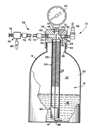
Figure 1 is a side elevational view partly in section
of a pressurized static whipping container employing the
principals of the present invention;
Figure 2 is an enlarged cross-sectional view of the
static whipping device employing the principals of the
present invantion connected to the pressurized container
cap of Figure l;
Figure 3 is an enlarged view of elements of the con-
tainer shown in Figure 2; and
Figure 4 is an exploded view of the static whipping
device of Figure 2.
Detailed Description of the Preferred Embodiment
Referring now to the drawings, and more particularly
to Figure 1, there is illustrated a pressurized static
whipping and dispensing container, indicated generally by
the numeral 10, employing the principals of the present
invention. The pressurized container 10 includes a side
wall 12, a bottom wall 14 and an interior chamber 16
which is adapted to hold a given amount of whippable liq- ,
uid 18 under pressure of a propellant gas which fills the
head space 22 above the liquid 18. A cap 24 is secured
to the:externally threaded neck of the container 10 by
mating screw threads 28 disposed in the male section 30
of cap 24. An 0-ring seal 32 is disposed between the
mouth of the neck 26 and the interior of the cap 24 to
: : prevent leakage of fluids. The cap 24 ls provided with a
combined charging and dispensing passageway or conduit
34, one end of which communicates with the chamber 16 and
.: ~ " -. . , : :
, . ~ , .. . .
C~3
--7--
the static means (discussed h0reinafter). The other end
of the passa~eway 34 communicates with a two-way valve
system~ indicated generally by the numeral 38, which is
screw threaded into the cap, as shown at 40. The two-way
valve system 38 controls both the delivery of the high
pressure charging or propellant gas 20 into the chamber
16 of the contai.ner for charging the latter and also the
dispensing of the pressuri.zed contents of the chamber.
The cap is also preferably provided with a co~ventional
pressure gauge 42 which is screw threaded into the top of
cap 24, as shown at 44 and communicates with chamber 16
through passageway 46. The cap is further preferably
provided with a conventional saftey vent valve 48 which
is screw threaded into the side of the cap, as shown at
50 and communicates with the chamber 16 through a pas-
sageway 25. Direct communication with passageway 46 is
blocked by a diaphragm 51.
A static means for intimate mixing of the whippable
liquid and the propellant or charging gas is disposed
within the chamber 16 and includes an elongated tubular
member 54 preferably made of a polymeric material such as
Nylon or pol~propylene, having the upper end 56, which is
preferably force fitted into internal bore 57 of the cap,
as shown at 58 but may be screw-threaded also. In this
manner, the upper end 56 communicates with the charging
and dispensing passage 34 in the cap 24. The length of
the tubular member 54 is selected with respect to the
height of the container so tha-t when attached to the cap,
the lower portion 60 e~tends into the whippable liquid 18
and is adjacent the bottom 14 of the chamber 16 while the
upper portion 56 is positioned in the head space 22 above
the liquid when the container is charged wlth the whip-
pable liquid and propellant.
An aperture 62 is disposed in the tubular member 54
so as to be positioned at a point in the head space 22
above the level of the given amount of whippable liquid
'
~;
:. ' ' - - ' . . .. ' :; : . .
.. '-' '' .: . ' " . ' ' ~ . ' ,
:,, . : '
''~
i'7'':~
--8--
18. The size of the aperture is between about 0.016 and
0.020 inches and is critical. It is selected so as to
permit a limited amount of propellant gas 20 to enter the
tubular member from the head space of the container as
discussed hereinafter. The aperture is formed by making
a hole in the tubular member 54 and then sealing the per-
imeter of the hole by heating it to the plastic's soften-
ing point whereby the plastic will lose its memory and
the hole will remain permanently open. Preferably, the
sealing is accomplished by putting a wire in the hole and
heating the wire to, at or near the softening point (but
below the charring point) of the plastic and then with-
drawing the wire after the softened material has cooled.
The static means also includes an elongated core mem-
ber 64 which has a multiplicity of semi-rigid fiber ele-
ments 66 extending generally radially about the core mem-
ber and which is slidably disposed within the tubular
member 54. The diameter of the fibers 66 disposed about
the core member 64 is preferably slightly larger than the
diameter of the tubular member 54 so as to be friction-
ally held in the tubular member when inserted. The fib-
ers preferably extend from a point at or below the aper-
ture 62 to a point adjacent or slightly below the upper
end of the tubular member 54 and the passage 34 of the
cap element. The lower end of the core 64 is providad
with a handle portion 68 to facilitate the insertion and
removal of the core member. It can be appreciated that
the core member is in the form of an elongated brush-like
device.
The two-way valve system 38 includes a conventional
fle~ible braided hose 70 attached at one end to the cap
by a conventional screw-threaded hose connector 72 and at
the end to a conventional two-way valve 74 also by a con-
ventional screw-threaded hose connector 76. The two-way
charging and dispensin~ valve 74 is conventional and
includes a push button valve assembly 78 and a charging
.. .. .. .
- : . , . ,
.: :, , , . .: .
.
~d~; 79
and dispensing nozzle 80.
In a non-limiting example, the pressure static whip-
ping and dispensing device of the present invention is
constructed using a stainless steel pressure container
5 having a volume of whippable liquid of two to five
quarts, and a stainless steel cap. The static whipping
device is ~ormed of Nylon having a length of about 7.25
inches, an outside diameter (O.D.) of 0.500 inches and an
inside diameter (I.D.) of 0.330 inches. The core member
10 is formed of stainless steel wire with spiral-wound Nylon
fibers. The aperture diameter is 0.01~ inches.
In producing a whippable food product, a given volume
of liquid whipping cream is introduced to the chamber of
the pressure container and thereafter the container is
15 charged with a propellant gas to a pressure of 200 to 220
psi. No agitation of the container is necessary to dis-
solve the propellant gas into the cream. When the opera-
tor desires to dispense whipped cream, the dispensing
push button is pressed. At this point, the propellant
20 gas pressure in the chamber causes the whippable liquid
to flow or syphon up the whipping tube and into contact
with the fibers of the core member (core brush). At the
same time, the propellant gas enters the aperture in the
whipping tube and contacts the liquid cream as the cream
25 level passes the aperture as best shown in Figure 3. The
result of the pre-agitation of the liquid cream by the
fibers prior to the aperture and the continued agitation
as the cream continues to rise together with the
increased or violent agitation caused by the introduction
30 of the propellant gas through the aperture causes an
intimate intermixing (as represented by the numeral 82 in
Figure 3) of the cream-liquid and gas. The cream and gas
continue to intermix as the mixture level rises to the
dispensing passage, and produces a whipped product as it
35 passes through the dispenslng nozzle by the expansion of
the propellant gas that is intermixed with the liquid
.. .
: `
-
--10--
cream. It can be appreciated that the tubular member
provides a venturi effect to the passaye of the whippable
liquid therethrough due to the restriction within the
passageway of the tubular member due to the bristles and
the core.
If the operator wishes to refill the pressure con-
tainer, the remaining head pressure is simply vented off
through the safety vent valve. The cap is removed and
fresh whippable liquid is added to the capacity of the
given amount. The cap is replaced and the container is
recharged with the propellant gas.
With respect to sanitation, it is of course necessary
upon occasion to dismantle the apparatus and clean all
parts. The design of the static means of the present
invention is such that the tube and core brush can be
easily and readily removed and cleaned or replaced. Fur-
thermore, because of the nature of the core brush~ it
serves to assist in cleaning the tubular member during
the removal process.
With respect to the size of the tubular aperture 62,
it can be appreciated that the diameter of the aperture
can vary as a function of the maximum propellant gas
pressure. However, when it is desirable to admit more
propellant gas to the tubular member, several small aper-
tures can be employed rather than a single larger aper-
ture. While the flow of propellant gas through the aper-
ture initially provides some assistance in the form of a -,
suction effect in raising the liquid level in the tubulat
member, the size of the aperture should not be so large
as to unreasonably reduce the propellant gas pressure.
While the invention has been described with respect
to preferred embodlments, it will be apparent to those
skilled in the art that changes and modifications may be
made without departing from the scope of the invention
herein involved in its broader aspects. Accordingly, it
is intended that all matter contained in the above
.
.: .
7~a
description, or shown in the accompanying drawing, shall
be interpreted as illustrative and not in a limiting
sense.
: . : - : .
, ` . : ,: ', ' .
', ,' ' ' ' , ' ' '
: ~ . . . .