Sélection de la langue

Search

Sommaire du brevet 2009906 

Énoncé de désistement de responsabilité concernant l'information provenant de tiers

Une partie des informations de ce site Web a été fournie par des sources externes. Le gouvernement du Canada n'assume aucune responsabilité concernant la précision, l'actualité ou la fiabilité des informations fournies par les sources externes. Les utilisateurs qui désirent employer cette information devraient consulter directement la source des informations. Le contenu fourni par les sources externes n'est pas assujetti aux exigences sur les langues officielles, la protection des renseignements personnels et l'accessibilité.

Disponibilité de l'Abrégé et des Revendications

L'apparition de différences dans le texte et l'image des Revendications et de l'Abrégé dépend du moment auquel le document est publié. Les textes des Revendications et de l'Abrégé sont affichés :

  • lorsque la demande peut être examinée par le public;
  • lorsque le brevet est émis (délivrance).
(12) Brevet: (11) CA 2009906
(54) Titre français: METHODE ET DISPOSITIF DE CIRCULATION AUTOMATIQUE DANS LES POSTES DE POMPAGE DES EAUX USEES
(54) Titre anglais: METHOD AND DEVICE FOR AUTOMATIC CIRCULATION IN WASTE WATER PUMP STATIONS
Statut: Réputé périmé
Données bibliographiques
(52) Classification canadienne des brevets (CCB):
  • 137/63
  • 137/78
(51) Classification internationale des brevets (CIB):
  • F04D 29/00 (2006.01)
  • B01F 5/02 (2006.01)
  • B01F 7/00 (2006.01)
  • B01F 15/02 (2006.01)
  • E03F 5/22 (2006.01)
  • F04B 53/10 (2006.01)
  • F04D 29/70 (2006.01)
(72) Inventeurs :
  • LANDQUIST, FOLKE (Suède)
(73) Titulaires :
  • ITT FLYGT AKTIEBOLAG (Suède)
(71) Demandeurs :
(74) Agent: SMART & BIGGAR
(74) Co-agent:
(45) Délivré: 1999-12-28
(22) Date de dépôt: 1990-02-13
(41) Mise à la disponibilité du public: 1990-08-21
Requête d'examen: 1995-01-25
Licence disponible: S.O.
(25) Langue des documents déposés: Anglais

Traité de coopération en matière de brevets (PCT): Non

(30) Données de priorité de la demande:
Numéro de la demande Pays / territoire Date
89-00597-9 Suède 1989-02-21

Abrégés

Abrégé anglais


The pressure side of the pump unit is provided with a valve (6)
which during certain periods opens a connection between the pump
and the pump station to obtain circulation in the station. The
valve (6) is opened and closed by a valve ball (9) which is
controlled by the pump pressure.

Revendications

Note : Les revendications sont présentées dans la langue officielle dans laquelle elles ont été soumises.


THE EMBODIMENTS OF THE INVENTION IN WHICH AN EXCLUSIVE
PROPERTY OR PRIVILEGE IS CLAIMED ARE DEFINED AS FOLLOWS:
1. A device for obtaining circulation in a sewage pump
water station containing one or several pump units, preferably
centrifugal pumps of the submersible type, which device
comprises mixer valves connected to one or several of the pump
units, which valves automatically during a certain limited
period (periods) connect the pressure side of a pump with the
pump station thus obtaining a circulation of the pumped medium
and where the alternate return connection to the pump station
is carried out by a valve comprising a cylinder formed part
connected to the pressure side of the pump and an outlet
nozzle, characterized in that to the cylinder formed part of
the valve there is sealingly attached a bellows which contains
a sealingly connected diaphragm and a valve element which, in
dependence of the pressure situation in the valve, in its one
rest position seals against a seat in the valve thus closing
the latter and which in its other rest position is contained
in a valve cup without hinderance to flow through the valve.
2. A device according to claim 1, characterized in that
the valve cup, which separates an interior space of the
bellows from a space between the valve cup and the diaphragm,
is provided with an opening which allows a medium to be
exchanged between the two spaces.
-5-


3. A device according to claim 1 or 2, characterized in
that bellows is filled with a damping medium such as oil.
4. A device according to claim 1, 2 or 3, characterized
in that the valve element is a ball.
5. A device according to any one of claims 1 to 4,
characterized in that the valve is provided with a connection
for air intake for delaying or controlling the closing time.
6. In combination:
a cylinder part with a flow channel connected to the
pressure side of a pump and having an outlet nozzle and a seat
in said flow channel;
a bellows sealingly attached to said part and
containing a sealingly connected diaphragm and valve cup; and
a valve element located within said diaphragm and
movable from a first position to a second position against
said seat depending on the flow in said channel.
7. The combination of claim 6 wherein said valve cup
includes an opening to permit a fluid medium to be exchanged
between an area located between said bellows and said cup and
an area between said diaphragm and said cup.
8. The combination of claim 7 wherein said fluid medium
is a damping medium such as oil.


-6-


9. The combination of claim 6, 7 or 8 wherein said
valve element is a ball.
-7-

Description

Note : Les descriptions sont présentées dans la langue officielle dans laquelle elles ont été soumises.


2009906
A METHOD AND DEVICE FOR AUTOMATIC CIRCULATION
IN A WASTE WATER PUMP STATION
BACKGROUND OF THE INVENTION
The invention relates to a device for providing
circulation in pump stations which are parts of a municipal
sewage system.
As disclosed in U.S. Patent 4,462,766, issued July
31, 1984, sludge banks occur in pump stations and other tanks
in a sewage system due to poor circulation. Sludge banks can
cause a number of problems including bad odors, risk of
explosions, corrosion problems, etc.
According to the foregoing Patent, the problems have
been solved by arranging a valve in the pump outlet, which is
opened temporarily thus obtaining a circulation and flushing
in the pump station. The sludge banks are dissolved and the
fluid is homogenized.
The adjustment of the valve has been electrically
controlled by means of a linear motor which acts upon a slide
in the valve. A disadvantage with this solution, in addition
to a relatively high cost, is that it easily becomes clogged
as the pumped medium normally contains large amounts of solid
bodies such as stones, rags and other objects. If a stone is
stuck in the valve slide, the electric motor may break down.
Another disadvantage is that the motor of the valve
is electrically driven which means specific installation
problems where explosive gas may occur.
SUMMARY OF THE INVENTION
An object of this invention is to provide a method
- 1 -
72432-49
a


2009906
and a device which in a simple and reliable way controls the
valve and which is less sensitive to clogging.
According to a broad aspect, the present invention
provides in combination: a cylinder part with a flow channel
connected to the pressure side of a pump and having an outlet
nozzle and a seat in said flow channel; a bellows sealingly
attached to said part and containing a sealingly connected
diaphragm and valve cup; and a valve element located within
said diaphragm and movable from a first position to a second
position against said seat depending on the flow in said
channel.
According to another aspect, the present invention
provides a device for obtaining circulation in a sewage pump
water station containing one or several pump units, preferably
centrifugal pumps of the submersible type, which device
comprises mixer valves connected to one or several of the pump
units, which valves automatically during a certain limited
period (periods) connect the pressure side of a pump with the
pump station thus obtaining a circulation of the pumped medium
and where the alternate return connection to the pump station
is carried out by a valve comprising a cylinder formed part
connected to the pressure side of the pump and an outlet
nozzle, characterized in that to the cylinder formed part of
the valve there is sealingly attached a bellows which contains
a sealingly connected diaphragm and a valve element which, in
dependence of the pressure situation in the valve, in its one
rest position seals against a seat in the valve thus closing
the latter and which in its other rest position is contained
- 2 -
72432-49


2009906
in a valve cup without hinderance to flow through the valve.
BRIEF DESCRIPTION OF THE DRAWINGS
Other objects, features and advantages of the
present invention will become more fully apparent from the
following detailed description of the preferred embodiment,
the appended claims and the accompanying drawing in which:
Fig. 1 shows a pump station with a pump unit and
attached valve; and
Figs. 2 to 4 show the principle design of the valve
in different operating positions.
DETAILED DESCRIPTION OF THE PREFERRED EMBODIMENT
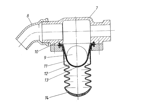
Referring now to the drawings, a pump station 1 with
a submersible pump unit 2 is connected to a pressure pipe 3.
The pump housing 4 has an inlet 5, and a mixing valve 6 is
mounted on the pump housing 4. A cylinder 7 is formed as part
of the valve 6 with its outlet 8. A valve ball 9 is
displaceable to its seat 10. A diaphragm 11 is located in a
cup 12 with an opening 13 and an attached bellows 14.
In operation, the valve 6 is normally closed and the
pumped medium is transported from the pump housing 4 into the
pressure pipe 3. The flow direction is shown by the Arrow A
in Fig. 1. During certain times, for instance at pump start,
the valve 6 is open, which means that a certain amount of the
pumped medium flows through the valve in the direction of
Arrow B, and provides a strong agitation in the pump station
to dislodge possible sludge banks. After a certain time, the
valve 6 is closed and the pumping takes place in the normal
way.
- 2a -
72432-49


2009906
The valve 6 includes the cylinder formed part 7 and
the outlet nozzle 8. A bellows 14 is connected to the
cylinder part 7, which bellows encloses a valve cup 12
containing a diaphragm 11 with a valve ball 9. The ball 9 is
arranged to be able to close the cylinder part 7 when it is
pressed against the seat 10 in part 7.
In Fig. 2, the valve 6 is shown in open position
which means that circulation takes place within the pump
station. The valve ball 9 in this position is out of the flow
path, not hindering
- 2b -
72432-49


2009906
F. Landquist-3 (Revision)
it. The flow through the part 7 then quickly creates an under
pressure which effects diaphragm 11 and causes a closing of the
valve after a certain time.
Since the diaphragm 11 is sealingly attached to the cylinder
part 7, the under pressure created in part 7 will urge the
diaphragm 11 with ball 9 to move upwards into the part 7 in
direction of arrow 9A. The movement of the diaphragm 11 into part
7 is prevented by the fact that the valve cup 12 and the bellows 14
are also sealingly attached in the part 7.
The valve cup 12 has an opening 13, which allows passage of a
damping medium, normally oil, contained within the bellows 14
moving in direction of arrow 14a, into the space between the cup 12
and the diaphragm 11 as shown by arrows l3a,b. The diaphragm 11
can then be sucked into the part 7. The speed of this movement is
decided by the area of the opening 13 and the magnitude of the
underpressure in the part 7.
Fig. 3 shows the position where the diaphragm 11 and the ball
are in progress moving into the flow F in the part 7. After a
little while the ball 9 has been moved so far into the flow in the
part 7, that the flowing medium presses the ball against the seat
as shown in Fig. 4, thus closing the valve. This is then kept
closed as long as pumping continues.
During this time the pump pressure prevails in the part 7 which
means that the diaphragm il is pressed back towards its initial
position at a speed which is decided by the flow rate of the
damping medium through the opening 13, back into the bellows 14.
Fig. 4 shows the valve in a closed position when the diaphragm has
reached its initial position. When the pumping is stopped, the
pressure goes down and the ball 9 resumes the position shown in
Fig. 2, thus opening the valve before the next pump start cycle.
In the above description, the valve ball is heavier than the
pumped medium such that the bellows, cup and diaphragm arrangement
are below the valve. The invention, however, contemplates an
embodiment wherein the ball has a density lower than that of the
-3-


2oossos
F. Landquist-3 (Revision)
pumped medium, and therefore the bellows device would be arranged
above the valve so that the ball comes to the surface for opening
of the valve before next pump start cycle.
According to another embodiment of the invention, an outer
conduit may be connected to the cylinder part 7, where additives
such as gas, chemicals, etc. can be sucked into the flow when the
valve is open. This outer conduit may also be used for letting in
air to delay or control the closing time at a simultaneous aeration
of the pumped medium.
In the foregoing description, the closing element is a valve
ball 9, however, other movable or turnable means may be used as
closing elements. The invention provides a very simple and
reliable device for controlling of the mixing valve for primarily
waste water pumping. The valve does not need any additional energy
source and can be easily set for different opening periods.
While the present invention has been disclosed in connection
with a preferred embodiment thereof, it should be understood that
there may be other embodiments which fall within the spirit and
scope of the invention as defined by the following claims.
-4-

Dessin représentatif
Une figure unique qui représente un dessin illustrant l'invention.
États administratifs

Pour une meilleure compréhension de l'état de la demande ou brevet qui figure sur cette page, la rubrique Mise en garde , et les descriptions de Brevet , États administratifs , Taxes périodiques et Historique des paiements devraient être consultées.

États administratifs

Titre Date
Date de délivrance prévu 1999-12-28
(22) Dépôt 1990-02-13
(41) Mise à la disponibilité du public 1990-08-21
Requête d'examen 1995-01-25
(45) Délivré 1999-12-28
Réputé périmé 2010-02-13
Correction de l'état expiré 2012-12-02

Historique d'abandonnement

Il n'y a pas d'historique d'abandonnement

Historique des paiements

Type de taxes Anniversaire Échéance Montant payé Date payée
Le dépôt d'une demande de brevet 0,00 $ 1990-02-13
Enregistrement de documents 0,00 $ 1990-12-03
Enregistrement de documents 0,00 $ 1991-07-26
Taxe de maintien en état - Demande - nouvelle loi 2 1992-02-13 100,00 $ 1992-01-14
Taxe de maintien en état - Demande - nouvelle loi 3 1993-02-15 100,00 $ 1992-10-22
Taxe de maintien en état - Demande - nouvelle loi 4 1994-02-14 100,00 $ 1993-12-07
Taxe de maintien en état - Demande - nouvelle loi 5 1995-02-13 150,00 $ 1995-01-18
Taxe de maintien en état - Demande - nouvelle loi 6 1996-02-13 150,00 $ 1996-01-15
Taxe de maintien en état - Demande - nouvelle loi 7 1997-02-13 150,00 $ 1997-01-16
Taxe de maintien en état - Demande - nouvelle loi 8 1998-02-13 150,00 $ 1998-01-16
Taxe de maintien en état - Demande - nouvelle loi 9 1999-02-15 150,00 $ 1999-01-18
Taxe finale 300,00 $ 1999-09-27
Taxe de maintien en état - brevet - nouvelle loi 10 2000-02-14 200,00 $ 2000-01-19
Taxe de maintien en état - brevet - nouvelle loi 11 2001-02-13 200,00 $ 2001-01-15
Taxe de maintien en état - brevet - nouvelle loi 12 2002-02-13 200,00 $ 2002-01-21
Taxe de maintien en état - brevet - nouvelle loi 13 2003-02-13 200,00 $ 2002-10-15
Taxe de maintien en état - brevet - nouvelle loi 14 2004-02-13 200,00 $ 2003-11-25
Taxe de maintien en état - brevet - nouvelle loi 15 2005-02-14 450,00 $ 2005-01-20
Taxe de maintien en état - brevet - nouvelle loi 16 2006-02-13 450,00 $ 2006-01-31
Taxe de maintien en état - brevet - nouvelle loi 17 2007-02-13 450,00 $ 2007-01-11
Taxe de maintien en état - brevet - nouvelle loi 18 2008-02-13 450,00 $ 2008-02-06
Titulaires au dossier

Les titulaires actuels et antérieures au dossier sont affichés en ordre alphabétique.

Titulaires actuels au dossier
ITT FLYGT AKTIEBOLAG
Titulaires antérieures au dossier
FLYGT AB
LANDQUIST, FOLKE
Les propriétaires antérieurs qui ne figurent pas dans la liste des « Propriétaires au dossier » apparaîtront dans d'autres documents au dossier.
Documents

Pour visionner les fichiers sélectionnés, entrer le code reCAPTCHA :


Pour visualiser une image, cliquer sur un lien dans la colonne description du document. Pour télécharger l'image (les images), cliquer l'une ou plusieurs cases à cocher dans la première colonne et ensuite cliquer sur le bouton "Télécharger sélection en format PDF (archive Zip)" ou le bouton "Télécharger sélection (en un fichier PDF fusionné)".

Liste des documents de brevet publiés et non publiés sur la BDBC .

Si vous avez des difficultés à accéder au contenu, veuillez communiquer avec le Centre de services à la clientèle au 1-866-997-1936, ou envoyer un courriel au Centre de service à la clientèle de l'OPIC.


Description du
Document 
Date
(yyyy-mm-dd) 
Nombre de pages   Taille de l'image (Ko) 
Page couverture 1993-11-27 1 16
Abrégé 1993-11-27 1 13
Revendications 1993-11-27 3 115
Dessins 1993-11-27 4 85
Description 1993-11-27 4 186
Description 1999-03-31 6 206
Revendications 1999-03-31 3 72
Dessins représentatifs 1999-12-10 1 14
Page couverture 1999-12-10 1 35
Correspondance 1999-09-27 1 35
Correspondance reliée au PCT 1990-09-14 1 43
Lettre du bureau 1990-08-21 1 45
Correspondance de la poursuite 1995-01-25 1 42
Lettre du bureau 1995-04-26 1 28
Correspondance de la poursuite 1998-12-07 2 64
Demande d'examen 1998-06-05 2 45
Taxes 1997-01-16 1 63
Taxes 1996-01-15 1 52
Taxes 1995-01-18 1 85
Taxes 1993-12-07 1 41
Taxes 1992-10-22 1 37
Taxes 1992-01-14 1 41