Sélection de la langue

Search

Sommaire du brevet 2012198 

Énoncé de désistement de responsabilité concernant l'information provenant de tiers

Une partie des informations de ce site Web a été fournie par des sources externes. Le gouvernement du Canada n'assume aucune responsabilité concernant la précision, l'actualité ou la fiabilité des informations fournies par les sources externes. Les utilisateurs qui désirent employer cette information devraient consulter directement la source des informations. Le contenu fourni par les sources externes n'est pas assujetti aux exigences sur les langues officielles, la protection des renseignements personnels et l'accessibilité.

Disponibilité de l'Abrégé et des Revendications

L'apparition de différences dans le texte et l'image des Revendications et de l'Abrégé dépend du moment auquel le document est publié. Les textes des Revendications et de l'Abrégé sont affichés :

  • lorsque la demande peut être examinée par le public;
  • lorsque le brevet est émis (délivrance).
(12) Brevet: (11) CA 2012198
(54) Titre français: DISPOSITIF ACCUMULATEUR AUTOVERROUILLABLE DE BILLETS DE BANQUE
(54) Titre anglais: SELF-LOCKING BILL ACCUMULATOR
Statut: Réputé périmé
Données bibliographiques
(52) Classification canadienne des brevets (CCB):
  • 270/173
(51) Classification internationale des brevets (CIB):
  • B65H 31/00 (2006.01)
  • G07D 11/00 (2006.01)
(72) Inventeurs :
  • HARRIS, ROBERT R. (Etats-Unis d'Amérique)
(73) Titulaires :
  • JEROME REMIEN CORPORATION (Etats-Unis d'Amérique)
(71) Demandeurs :
(74) Agent: BARRIGAR & MOSS
(74) Co-agent:
(45) Délivré: 1994-08-23
(22) Date de dépôt: 1990-03-14
(41) Mise à la disponibilité du public: 1990-11-11
Requête d'examen: 1991-04-08
Licence disponible: S.O.
(25) Langue des documents déposés: Anglais

Traité de coopération en matière de brevets (PCT): Non

(30) Données de priorité de la demande:
Numéro de la demande Pays / territoire Date
07/350,306 Etats-Unis d'Amérique 1989-05-11

Abrégés

Abrégé anglais


A self-locking bill accumulator having
tamper-proof features is provided for use with a dollar
bill processing machine. During use, the bill
accumulator is mounted to a bill processing machine.
The accumulator has a double locking feature whereby
rotation of an outer lock by means of a key is required
in order to detach and remove the bill accumulator from
the dollar bill processing machine. This rotation of
the outer lock occurs prior to removal of the bill
accumulator and causes a corresponding rotation of an
inner lock, which in turn positively locks the bill
accumulator to protect bills in the accumulator from
pilferage after removal. Upon removal of the bill
accumulator, the outer lock becomes disengaged from the
inner lock such that a separate key is required in
order to "unlock" the bill accumulator and remove the
bills.

Revendications

Note : Les revendications sont présentées dans la langue officielle dans laquelle elles ont été soumises.


WHAT IS CLAIMED IS:
1. A bill accumulator system for receiving and
storing bills, comprising:
an outer housing having an open face for
receiving bills from a bill validator;
an inner housing having an open face for
receiving and storing bills inside the inner housing,
rotatably mounted inside the outer housing;
first actuating means mounted to at least one
of the inner and outer housings for rotating the inner
housing relative to the outer housing, comprising an
inner locking means for selectively locking the inner
housing into an open position for receiving bills in
which the open face of the inner housing corresponds to
the open face of the outer housing, and a closed
position for blocking the passage of bills in which the
open face of the inner housing points away from the
open face of the outer housing;
second actuating means engageable to the
first actuating means for driving the first actuating
means, comprising a first key means engageable to the
inner locking means and a second locking means for
selectively locking the second actuating means to the
first actuating means as the inner housing is rotated
to its open position, and for releasing the first
actuating means from the second actuating means as the
inner housing is rotated to its closed position; and
means for mounting the bill accumulator
system onto a bill validator.

2. The bill accumulator system of claim 1
wherein the open face of the outer housing comprises
two coplanar rectangular edges defining an opening
which is slightly longer, and slightly narrower, than
the surface of a dollar bill.


- 9 -


3. The bill accumulator system of claim 1
wherein the open face of the inner housing comprises
two coplanar rectangular edges defining an opening
which is slightly longer, and slightly narrower, than
the surface of a dollar bill.

4. The bill accumulator system of claim 3
wherein the inner housing comprises means for
maintaining bills stored therein in a substantially
flat, stacked configuration.

5. The bill accumulator system of claim 4
wherein the means for maintaining bills in a
substantially flat, stacked position comprises a
spring-loaded plate inside the inner housing positioned
substantially parallel to the open face.

6. The bill accumulator system of claim 4
wherein the means for maintaining bills in a
substantially flat position comprises a foam rubber
piece inside the inner housing having a planar surface
which is substantially parallel to the open face.

7. The bill accumulator system of claim 1
wherein the second actuating means further comprises
key means for engaging the second locking means.

8. The bill accumulator system of claim 1
wherein the means for mounting the bill accumulator
system onto a bill validator includes a mounting member
for permanently mounting the second actuating means
onto the bill validator.

9. The bill accumulator system of claim 1
wherein the means for mounting the bill accumulator

- 10 -


system onto a bill validator includes a mounting slot
in the outer housing of the bill validator adapted to
receive a pivotal mounting shaft which is permanently
connected to the bill validator.

10. The bill accumulator system of claim 1
wherein the first actuating means is securely mounted
to an end of the outer housing and permanently engaged
to a corresponding end of the inner housing.

11. A bill accumulator system for receiving and
storing bills, comprising:
an outer housing having an opening for
receiving bills from a bill validator, adapted to be
mounted to a bill validator;
an inner housing having an opening for
receiving and storing bills, rotatably mounted inside
the outer housing;
first actuating means mounted to the outer
housing and engaged to the inner housing for rotating
the inner housing relative to the outer housing,
comprising an inner locking means for selectively
locking the inner housing in an open position for
receiving bills in which the opening in the inner
housing corresponds to the opening in the outer
housing, and a closed position for blocking the passage
of bills in which the opening in the inner housing
faces away from the opening in the outer housing;
the inner locking means adapted to be engaged
by a first key means;
the first actuating means adapted to be
engaged by a second actuating means which is
permanently mounted to the bill validator and which
includes the first key means and a second locking means
for selectively locking the second actuating means to

-11-


the first actuating means as the inner housing is
rotated to its open position, and for releasing the
first actuating means from the second actuating means
as the inner housing is rotated to its closed position.

12. A bill accumulator system for receiving and
storing bills, comprising:
an outer housing having a substantially
rectangular opening which is slightly longer and
slightly narrower than the surface of a dollar bill;
an inner housing having a substantially
rectangular opening which is slightly longer and
slightly narrower than the surface of a dollar bill,
rotatably mounted inside the outer housing;
first actuating means mounted to the outer
housing and engaged to the inner housing for rotating
the inner housing relative to the outer housing,
comprising an inner locking means for selectively
locking the inner housing in an open position in which
the opening in the inner housing corresponds to the
opening in the outer housing, and a closed position in
which the opening in the inner housing faces away from
the opening in the outer housing.
second actuating means engageable to the
first actuating means for driving the first actuating
means, comprising a first key means engageable to the
inner locking means and a second locking means for
selectively locking the second actuating means to the
first actuating means as the inner housing is rotated
to its open position, and for releasing the first
actuating means from the second actuating means as the
inner housing is rotated to its closed position;
key means for engaging the second locking
means; and


- 12 -


means for permanently mounting the second
actuating means to a bill processing machine.


- 13 -

Description

Note : Les descriptions sont présentées dans la langue officielle dans laquelle elles ont été soumises.


- 20~2~


FIELD OF THE INVENTION
This invention relates to a self-locking bill
accumulator system having tamper-proof features, for
use in vending machines.

BACKGROUND AND SUMMARY OF THE INVENTION
Security devices and systems for use in
coin-operating vending machines are well known in the
art. Typically, these devices have the ability to
accept a variety of different coin sizes and are
adaptable to a wide variety of coin-operated vending
machines. Examples of these security devices and
systems are disclosed in U.S. Patent 4,267,962 and
U.S. Patent 4,291,831. In both cases, coins are
deposited into a vending machine and a selection of
merchandise is made. The coins pass through a series
of stations in the machine which totalize and register
a credit for merchandise. The coins then pass into the
security device which, in both cases, includes an upper
inlet portion and a lower coin storage bag.
The upper inlet portion in each case includes
generally an inlet slot and two locking mechanisms. A
first locking mechanism is used for locking the inlet
portion of the security device into a receiving
position on the vending machine. A second locking
mechanism is used for locking the coin storage bag into

20121~

a receiving position on the inlet portion. The first
locking mechanism is engaged by a first key. When the
key is turned in order to remove the security device
from the vending machine, there is a corresponding
movement of an internal closure mechanism which
operates to block off the inlet slot. Thereafter,
between the time the security device is removed from
the vending machine and the time it reaches
headquarters for emptying, it is not possible to either
insert coins or remove coins from the security device.
The coins contained in the security device are thereby
protected from pilferage during transportation of the
device.
Once the security device reaches head-
quarters, a second key is engaged to the second locking
mechanism in order to separate the coin storage bag
from the upper inlet portion, whereby the bag can be
emptied and replaced.
As the prices of vending machine merchandise
have risen, vending machines which accept bills in
place of or in addition to coins have become
increasingly popular. Accordingly, there is a need for
a bill accumulating system which protects dollar bills
from pilferage during transportation of the bill
accumulating device. As with the security devices
previously used for coins, the bill device must be
lightweight and durable, and must be adaptable to a
wide variety of vending machines.
Accordingly, the present invention provides a
self-locking bill accumulator system which meets the
foregoing requirements. The device in accordance with
the invention will freely accept a large volume of
bills and can be used to collect bills of different
denominations. Furthermore, the device is reliable and
durable, and can be constructed from relatively
inexpensive and lightweight materials.
- 2 -


2Q12198


BRIEF DESCRIPTION OF THE FIGURES
FIGS. 1 and 2 illustrate the bill accumulatorof the invention in its operational position for
receiving bills, mounted onto a bill validator.
FIG. 3 shows the bill accumulating portion as
it is being removed from the bill validator. The outer
locking mechanism remains mounted to the bill validator
as shown.
FIG. 4 shows a bill validator after the bill
accumulator of the invention has been removed, except
for the outer locking mechanism.
FIG. 5 shows a bill accumulator of the
invention in which the outer locking mechanism has been
detached from the inner locking mechanism by turning
the key as shown. The turning of the key also causes
the bill accumulator to lock into the closed position
shown.
FIGS. 6 and 7 illustrate the use of a second
key inserted into the inner locking mechanism to reopen
the bill accumulating portion to allow removal of the
bills therein.
FIG. 8 is an outside view of the mounting
member for the outer locking mechanism shown in FIG. 4.
FIG. 9 is an end view of the bill
accumulating portion of the bill accumulator of the
invention, illustrating the inner locking mechanism.
FIG. 10 is an inside end view of the outer
locking mechanism and mounting member shown in FIGS. 4
and 5.
FIG. 11 is a sectional view of the bill
accumulator of the invention, showing in detail how the
actuating mechanisms interconnect with one another.

~0121~8
-


DETAILED DESCRIPTION OF A PREFERRED EMBODIMENT
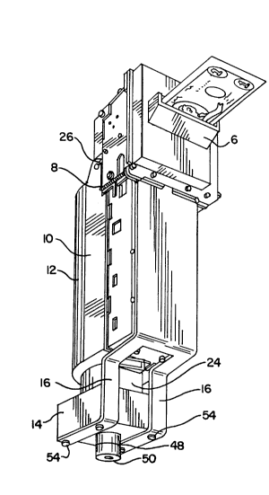
Referring to FIGS. 1-3, a bill accumulator
system 10 of the invention is provided for mounting
onto a bill validator 8 which in turn is mounted onto
the inside of a vending machine or other bill
processing machine (not shown). The bill accumulator
system 10 includes a bill accumulating portion 12 which
can be removed from the bill validator 8, and an outer
mounting member 14 which remains permanently secured to
the mounting brackets 16 extending from the bill
validator 8.
Referring now to FIGS. 5-7, the bill
accumulating portion 12 includes an outer housing 20,
an inner housing 22 rotatably mounted to the inside of
the outer housing 20, and a first actuating mechanism
24 mounted to the outer housing 20 and connected to the
inner housing 22, for rotating the inner housing 22
relative to the outer housing 20. The outer housing 20
includes a pair of mounting brackets 26 for mounting
the bill accumulating portion 12 onto the bill
validator 8, and an open face 28 having two coplanar
rectangular edges 30 which define an opening which is
slightly narrower and slightly longer than the surface
of a dollar bill 32 as shown in FIG. 7.
The inner housing 22 also includes an open
face 34 having two coplanar rectangular edges 36 which
define an opening which is slightly narrower and
slightly longer than the surface of a dollar bill 32 as
shown in FIGS. 6 and 7. The outer housing 20 and the
inner housing 22 are preferably semi-cylindrical in
shape. This facilitates rotation of the inner housing
22 relative to the outer housing 20 between an open
position for receiving and storing bills in which the

~0121~8


open face 34 of the inner housing 22 corresponds with
the open face 28 of the outer housing 20 as shown in
FIG. 7, and a closed position for blocking the passage
of bills in which the open face 34 of the inner housing
22 points away from the open face 28 of the outer
housing 20 as shown in FIG. 6.
During operation, the inner housing 22 is in
the open position such that the open face 34 of the
inner housing 22 and the open face 28 of the outer
housing 20 both face the bill validator 8. When a bill
is inserted into the slot 6 shown in FIG. 1, it is
first validated and is then passed into a long and
narrow section 7 of the bill validator 8 whereupon the
bill comes to rest with one surface facing the ejector
bar 9 of the bill validator 8 and the opposite surface
facing the open faces 34 and 28 of the inner and outer
housings of the bill accumulator 10. At this point,
the ejector bar operates by a mechanism well known in
the art to push the bill out of the bill validator,
through the open faces 34 and 28, and into the inner
housing of the bill accumulator 10.
The bills are maintained in the inner housing
in a substantially flat and stacked position by the
operation of a substantially flat support surface 40,
as shown in FIG. 7, which urges the bills 32 against
the inner surfaces of the coplanar edges 36 of the open
face 34 of the inner housing 22. The support surface
40 may be an outer surface of a spring-loaded plate
mounted inside the inner housing 22, or may
alternatively be a substantially flat surface of a foam
rubber insert. Other mechanisms for supporting the
bills are also possible, so long as the support is
sufficient to maintain the bills in a substantially
flat stacked configuration.

2G~L21S8


The first actuating mechanism 24, shown in
FIGS. 7 and 9, is mounted to the outer housing 20 by
means of a mounting member 42. The first actuating
mechanism 24 includes a stud 43 which is engaged to an
end of the inner housing 22 as shown in FIG. 11, and
includes an inner locking mechanism 44 positioned along
the stud 43. When driven by the rotation of a first
key stem 46 inserted into the inner locking mechanism
44, the first actuating mechanism 24 effects rotation
of the inner housing 22 between two locked positions,
an open position as shown in FIG. 7 and a closed
position as shown in FIG. 5.
During operation, the first actuating
mechanism 24 is engaged by a second actuating mechanism
48 which is mounted by means of a mounting member 14 as
shown in FIGS. 1 and 2. The second actuating mechanism
48 includes a first key stem 46 engageable to the inner
locking mechanism 44 as shown in FIGS. 3, 5 and 11, and
a second locking mechanism 50 which is driven by
rotation of a second key 52 between a locked position
in which the second actuating mechanism 48 and the
first actuating mechanism 24 are locked together, and
an unlocked position in which the first actuating
mechanism 24 is released from the second actuating
mechanism 48.
The rotation of the second key 52 between the
locked and unlocked positions effects a corresponding
rotation of the first key stem 46 such as to cause
rotation of the inner housing 22 between its open and
closed positions. Thus, when the second key 52 is
rotated such as to cause ths second actuating mechanism
48 and the first actuating mechanism 24 to lock
together, there is a corresponding rotation of the

2012~98


first key stem 46, causing the inner housing 22 to
rotate and to become locked in its open position for
the accumulation of bills from the bill validator 8 as
shown in FIGS. 1 and 2. Thereafter, when the second
key 52 is rotated such as to cause the second actuating
mechanism 48 and the first actuating mechanism 24 to
become disengaged as shown in FIG. 3, there is a
corresponding rotation of the first key stem 46 causing
the inner housing 22 to rotate and to become locked in
its closed position. There is no way to remove the
bill accumulating portion 12 from the bill validator 8
without first locking the inner housing in its closed
position, because the movement of the key 52 which is
required to disconnect the bill accumulating portion
causes a corresponding rotation of the inner housing 22
to its closed and locked position.
Typically, the route man will have in his
possession the second key 52 which is required to
remove the bill accumulating portion 12 from the bill
validator 8. Because the removal exercise also causes
a corresponding rotation and locking of the inner
housing 22, the route man does not have access to the
bills stored in the inner housing 22. The mounting
member 14 which contains the second actuating mechanism
48 remains permanently mounted to the brackets 16 which
extend from the bill validator 8, such as by the four
rivets 54 shown in FIG. 8. Thus, the only time that
the second actuating mechanism 48 can be used to reopen
the bill accumulating portion 12 is when the bill
accumulating portion 12 is reinstalled and locked into
place with its open faces 34 and 28 facing the bill
validator 8.
When the bill accumulating portion 12 reaches
headquarters, a key 60 which has a key stem identical

20121~


to the key stem 46 of the second actuating mechanism
48, can be used to unlock the inner housing 22 and
rotate the inner housing 22 to its open position as
shown in FIGS. 6 and 7. The inner housing 22 may then
be emptied and closed, and given back to the route man
for reinstallation in the bill processing machine.
Although the invention has been described
above with a certain degree of particularity, it should
be understood that this disclosure has been made only
by way of example. Consequently, numerous changes in
the details of construction and in the combination and
arrangement of the components, as well as in the
possible modes of utilization in accordance with this
invention will be apparent to those familiar with the
art, and may be resorted to without departing from the
scope of the invention.

Dessin représentatif
Une figure unique qui représente un dessin illustrant l'invention.
États administratifs

Pour une meilleure compréhension de l'état de la demande ou brevet qui figure sur cette page, la rubrique Mise en garde , et les descriptions de Brevet , États administratifs , Taxes périodiques et Historique des paiements devraient être consultées.

États administratifs

Titre Date
Date de délivrance prévu 1994-08-23
(22) Dépôt 1990-03-14
(41) Mise à la disponibilité du public 1990-11-11
Requête d'examen 1991-04-08
(45) Délivré 1994-08-23
Réputé périmé 1998-03-16

Historique d'abandonnement

Il n'y a pas d'historique d'abandonnement

Historique des paiements

Type de taxes Anniversaire Échéance Montant payé Date payée
Le dépôt d'une demande de brevet 0,00 $ 1990-03-14
Enregistrement de documents 0,00 $ 1990-09-19
Taxe de maintien en état - Demande - nouvelle loi 2 1992-03-16 50,00 $ 1992-03-10
Taxe de maintien en état - Demande - nouvelle loi 3 1993-03-15 50,00 $ 1993-03-02
Taxe de maintien en état - Demande - nouvelle loi 4 1994-03-14 50,00 $ 1994-03-08
Taxe de maintien en état - brevet - nouvelle loi 5 1995-03-14 75,00 $ 1995-03-09
Taxe de maintien en état - brevet - nouvelle loi 6 1996-03-14 75,00 $ 1996-02-20
Titulaires au dossier

Les titulaires actuels et antérieures au dossier sont affichés en ordre alphabétique.

Titulaires actuels au dossier
JEROME REMIEN CORPORATION
Titulaires antérieures au dossier
HARRIS, ROBERT R.
Les propriétaires antérieurs qui ne figurent pas dans la liste des « Propriétaires au dossier » apparaîtront dans d'autres documents au dossier.
Documents

Pour visionner les fichiers sélectionnés, entrer le code reCAPTCHA :


Pour visualiser une image, cliquer sur un lien dans la colonne description du document. Pour télécharger l'image (les images), cliquer l'une ou plusieurs cases à cocher dans la première colonne et ensuite cliquer sur le bouton "Télécharger sélection en format PDF (archive Zip)" ou le bouton "Télécharger sélection (en un fichier PDF fusionné)".

Liste des documents de brevet publiés et non publiés sur la BDBC .

Si vous avez des difficultés à accéder au contenu, veuillez communiquer avec le Centre de services à la clientèle au 1-866-997-1936, ou envoyer un courriel au Centre de service à la clientèle de l'OPIC.


Description du
Document 
Date
(yyyy-mm-dd) 
Nombre de pages   Taille de l'image (Ko) 
Page couverture 1996-02-05 1 16
Abrégé 1994-08-23 1 22
Description 1994-08-23 8 305
Revendications 1994-08-23 5 163
Dessins 1994-08-23 3 132
Page couverture 1993-12-04 1 15
Abrégé 1993-12-04 1 23
Revendications 1993-12-04 5 165
Dessins 1993-12-04 3 135
Description 1993-12-04 8 311
Dessins représentatifs 1999-07-30 1 19
Lettre du bureau 1991-06-28 1 32
Correspondance reliée au PCT 1994-06-08 2 79
Demande d'examen 1993-10-15 2 99
Correspondance de la poursuite 1991-04-08 1 44
Correspondance de la poursuite 1994-01-12 4 160
Taxes 1996-02-20 1 45
Taxes 1995-03-09 1 60
Taxes 1994-03-08 1 38
Taxes 1993-03-02 1 24
Taxes 1992-03-10 1 27
Taxes 1992-04-03 1 31