Note : Les descriptions sont présentées dans la langue officielle dans laquelle elles ont été soumises.
20 1 338~
The present invention relates to a
recording/playback head which can be used with storage
media capable of optical and magnetic recording and
reproduction, and more particularly to a recording/playback
head used with magnetic disks, for example, hard disks.
In recent years, the amount of information has
continued to increase steadily, and magnetic disks, optical
disks and other media capable of relatively high-density
recording are being used in place of conventional paper as
storage media. These storage media with read/write
capability are requiring greater recording densities.
Greater recording density is achieved on magnetic
disks, for example those used in hard disks, by improving
the magnetic disk itself and the magnetic head. The
magnetic disk is being improved through the development of
media with high, stable coercivity, and the materials being
used include Co metal and Co-Ni, Co-Ti, Co-Fe, Co-Cr, Co-
Ni-Cr and Co-P alloys.
Since the magnetic heads must have the capability
of writing information to a magnetic disk with a larger
coercivity, they must be able to form a large magnetic
field on the storage medium surface. Further, since the
recording frequency cannot be lowered when recording on the
magnetic disk, a floating type magnetic head is used, and
the distance that the head floats above the magnetic disk
is minimized so that it is as close as possible to the
storage medium surface.
However, at any frequency, there is a limit to how
large a magnetic field can be generated by a floating type
magnetic head, so that magnetic disks with a very large
coercivity cannot be used. This can cause difficulties in
performing recording at sufficiently high recording
densities. Moreover, in configurations in which the
magnetic head is as close as possible to the magnetic disk,
the effect of dust between the magnetic disk surface and
the magnetic head becomes greater and there is a much
greater danger of head crash.
201 338~
.
According to the present invention, there is
provided an optical/magnetic composite head comprising: a
floating type magnetic head that is supported in a non-
contact position with regard to a rotatable recording
medium and impresses a magnetic field on said recording
medium so as to perform recording operations; an optical
head located on said magnetic head facing said recording
medium and said optical head including; a laser beam-
generating means for directing a laser beam on to said
recording medium via an optical waveguide path, wherein
said magnetic head and said optical head are integrated
into one unit, said laser beam being directed so as to
irradiate on a point on said recording medium where said
magnetic field is impressed from said magnetic head.
When magnetically recording on a storage medium,
the laser beam emitted by the laser beam-generating means
passes through the waveguide of the optical waveguide path
and is directed to the optical system of the optical
waveguide path. The laser beam is then irradiated on the
point on the storage medium where the magnetic field is
impressed by the magnetic recording head. By this means,
the temperature of the point on the storage medium
irradiated by the laser beam rises, causing the coercivity
to drop. Recording is then performed by the magnetic field
impressed from the magnetic head. With the photomagnetic
composite head of the present invention recording is
performed under a condition where the coercivity of the
storage medium is lowered, so that a high-density recording
can be attained by using a storage medium with a high
coercivity on which recording cannot be performed by a
magnetic head alone. Integration of the magnetic head and
optical head into one unit facilitates high-speed access
during recording. As mentioned above, since recording is
performed by a magnetic field in a state in which the
coercivity of the storage medium is lowered, it is
unnecessary for the photomagnetic composite head to be very
close to the recording medium. Accordingly, the effect of
~.~
20 1 3385
-
dust between the magnetic disk and the photomagnetic
composite head as well as the danger of head crash can be
reduced.
Thus, the invention described herein makes
possible the objectives of (1) providing a photomagnetic
composite head by which recording can be performed under
conditions in which the coercivity of the recording medium
has been lowered by the laser beam during magnetic
recording on a recording medium, which makes it possible to
achieve high density recording by using a recording medium
with a high coercivity; and (2) providing a photomagnetic
composite head by which recording and reading can be
carried out on and from the magnetic disk without the
photomagnetic composite head being very close to the
recording medium, so that the effect of dust between the
magnetic disk and the photomagnetic composite head and the
danger of head crash can be reduced.
In drawings which illustrate an embodiment of the
present invention,
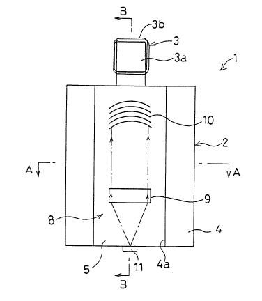
Figure 1 is a top plan view of a photomagnetic
composite head in accordance with an embodiment of the
present invention;
Figure 2 is a cross-sectional view along line A-A
of Figure 1;
Figure 3 is a cross-sectional view along line B-B
of Figure 1; and
Figure 4 is a perspective view of the
photomagnetic composite head of Figure 1.
Referring to Figures 1, 2, 3 and 4, a
photomagnetic composite head 1 of the present invention
comprises a magnetic head 2 and an optical head 8
integrated into one body.
The magnetic head 2 is composed of a magnetic head
part 3 and a slider part 4. The magnetic head part 3 and
slider part 4 can be formed as a unitary structure from a
ferrite block made from an appropriate head material, such
as Mn-Zn.
~'
201 3385
The surface of the slider part 4 opposing a
magnetic disk 12 functioning as a recording medium, as
shown more clearly in Figure 3, has a groove 4a extending
along the length of the slider part 4. The magnetic head
part 3 is located at one end of the slider part 4. A bar-
shaped head core 3a of the magnetic head part 3 projects
upwardly and has a coil 3b wrapped there around to impress
a magnetic field m on the storage medium surface of the
magnetic disk 12. The head core 3a of the magnetic head
part 3 need not be formed from the same material as the
slider part 4 and may be formed from some other head
material.
The groove 4a in the slider part 4 has an optical
waveguide path 5. As shown more clearly in Figures 2 and
3, the optical waveguide path 5 has a glass substrate 6 and
a waveguide 7 to direct a laser beam. The waveguide 7 is
formed of LiNbO3 on the glass substrate 6. An optical head
8 is mounted on the waveguide 7 and is composed of a
Fresnel lens 9 which makes parallel a laser beam that is
emitted by a laser diode 11 and passes through the
waveguide 7, and a convergence grating coupler 10 which
diffracts the laser beam that has passed through the
Fresnel lens 9 so as to converge on the magnetic disk 12.
The point of convergence of the laser beam b on the
magnetic disk 12 and the point where the magnetic field m
is impressed by the magnetic head part 3 are the same.
The laser diode 11 is mounted as a laser beam
generating means on the end of the slider part 4 opposite
the magnetic head part 3 in the optical waveguide path 5.
The above-mentioned optical waveguide path 5, Fresnel lens
9, convergence grating coupler 10 and laser diode 11 make
up the optical head 8.
The photomagnetic composite head 1 with the above
configuration is retained by a suspension (not shown) to
form a floating type head which does not come into contact
with the magnetic disk 12 used as the storage medium. The
photomagnetic composite head 1 is retained at a distance of
~,
- 201 338~
several microns from the magnetic disk 12 by the suction
force of air that occurs between the magnetic disk 12 and
the slider part 4 of the photomagnetic composite head 1
when the magnetic disk 12 is rotated. The distance between
the magnetic disk 12 and the photomagnetic composite head
1 is determined by factors such as the surface area of the
slider part 4, the weight of the photomagnetic composite
head 1, the number of revolutions of the magnetic disk 12,
the elastic modulus of the suspension, and the like. By
using a floating type construction, the distance between
the photomagnetic composite head 1 and the magnetic disk 12
is kept at a known constant, so that it is easy to match up
the convergence point of the laser beam b and the point
where the magnetic field m is impressed by the magnetic
head 2, as shown more clearly in Figure 3.
The storage medium part of the magnetic disk 12
can be formed of Co metal, or alloys of Co such as Co-Ni,
Co-Ti, Co-Fe, Co-Cr, Co-Ni-Cr and Co-P. The storage medium
part has a high coercivity.
In the above configuration, the magnetic head 2
and optical head 8 are operated while recording to the
rotating magnetic disk 12 by the photomagnetic composite
head 1. A modulated magnetic field m based on the
recording signal is impressed on the magnetic disk 12 by
the magnetic head 2, and at the same time, a laser beam b
is irradiated by the optical head 8 on the point of the
magnetic disk 12 where the magnetic field m is impressed by
the magnetic head 2. The laser beam emitted by the laser
diode 11 of the optical head 8 passes through the waveguide
7 of the optical waveguide path 5, and is made parallel by
the Fresnel lens 9, after which it is diffracted by the
convergence grating coupler 10 so as to be converged on the
magnetic disk 12.
When the laser beam b is irradiated on the
magnetic disk 12 as described above, the temperature of the
point irradiated by the laser beam b rises and the
coercivity drops. Recording is then performed by the
*~
201 338~
magnetic field m impressed on the point by the magnetic
head 2. Accordingly, a magnetic disk 12 with a large
coercivity can be used, thereby facilitating high density
recording.
Reproduction is performed by the magnetic head 2
reading the information recorded on the magnetic disk 12.
This operation is performed without operating the optical
head 8 and lowering the coercivity of the magnetic disk 12.
While the magnetic disk 12 is rotating, the
suction force of air that occurs between the magnetic disk
12 and the slider part 4 retains the photomagnetic
composite head 1 at a distance of several microns from the
magnetic disk 12. This photomagnetic composite head 1 of
the present invention is capable of performing magnetic
recording to the magnetic disk 12 at this distance because
the coercivity of the magnetic disk 12 is reduced by the
laser beam b. In the case of magnetic recording with only
a magnetic disk 12, as is known in the prior art, increased
distances between the magnetic disk 12 and the magnetic
head during reading of the magnetic disk 12, reduces the
reading sensitivity. Accordingly, in the prior art, the
gap between the magnetic disk 12 and the magnetic head must
be reduced to within l~m thereby increasing the effect of
dust between the magnetic disk 12 and the magnetic head, as
well as the danger of head crash. In accordance with the
present invention, the distance between the magnetic disk
12 and the photomagnetic composite head 12 is increased to
minimize the latter effects without reducing the reading
sensitivity.
Furthermore, the optical waveguide path 5 is
protected in the groove 4a of the slider part 4 even if the
magnetic head 2 should suffer head crash. Moreover, the
integration of the magnetic head 2 and optical head 8 into
a single unit facilitates high-speed access during
recording.
As described above, according to this invention,
recording can be performed under conditions in which the
~i
201 3385
-
coercivity of the recording medium has been lowered by the
laser beam during magnetic recording on a recording medium,
thus making it possible to achieve high density recording
by using a recording medium with a high coercivity.
Moreover, since recording and reading can be performed on
and from the magnetic disk, respectively, without placing
the photomagnetic composite head too closely to the
recording medium, the effect of dust between the magnetic
disk and the photomagnetic composite head and the danger of
head crash can be reduced.
~.~ .
..,