Sélection de la langue

Search

Sommaire du brevet 2013551 

Énoncé de désistement de responsabilité concernant l'information provenant de tiers

Une partie des informations de ce site Web a été fournie par des sources externes. Le gouvernement du Canada n'assume aucune responsabilité concernant la précision, l'actualité ou la fiabilité des informations fournies par les sources externes. Les utilisateurs qui désirent employer cette information devraient consulter directement la source des informations. Le contenu fourni par les sources externes n'est pas assujetti aux exigences sur les langues officielles, la protection des renseignements personnels et l'accessibilité.

Disponibilité de l'Abrégé et des Revendications

L'apparition de différences dans le texte et l'image des Revendications et de l'Abrégé dépend du moment auquel le document est publié. Les textes des Revendications et de l'Abrégé sont affichés :

  • lorsque la demande peut être examinée par le public;
  • lorsque le brevet est émis (délivrance).
(12) Brevet: (11) CA 2013551
(54) Titre français: JOINT D'ETANCHEITE POUR BASSE PRESSION ET CAPTEUR GARNI DUDIT JOINT
(54) Titre anglais: REDUCED PRESSURE SEALS AND DEBRIS TRAP INCLUDING SUCH SEALS
Statut: Réputé périmé
Données bibliographiques
(52) Classification canadienne des brevets (CCB):
  • 182/102
  • 277/69
(51) Classification internationale des brevets (CIB):
  • B01D 35/02 (2006.01)
  • B01D 29/35 (2006.01)
  • B01D 35/147 (2006.01)
  • F16J 15/02 (2006.01)
  • F16J 15/10 (2006.01)
(72) Inventeurs :
  • KALLENBACH, DIETER H. F. (Afrique du Sud)
  • HELGE JOCHEN SCHNEIDER (Afrique du Sud)
(73) Titulaires :
  • ZODIAC POOL CARE, INC. (Etats-Unis d'Amérique)
(71) Demandeurs :
(74) Agent: NORTON ROSE FULBRIGHT CANADA LLP/S.E.N.C.R.L., S.R.L.
(74) Co-agent:
(45) Délivré: 1998-06-23
(22) Date de dépôt: 1990-03-30
(41) Mise à la disponibilité du public: 1990-09-30
Requête d'examen: 1991-12-19
Licence disponible: S.O.
(25) Langue des documents déposés: Anglais

Traité de coopération en matière de brevets (PCT): Non

(30) Données de priorité de la demande:
Numéro de la demande Pays / territoire Date
89/2391 Afrique du Sud 1989-03-31
89/6665 Afrique du Sud 1989-08-31
89/7420 Afrique du Sud 1989-09-29

Abrégés

Abrégé français

La présente invention porte sur l'étanchéité de pièces d'équipement donnant passage à un liquide sous pression réduite et sur l'incorporation d'une lèvre d'étanchéité entre les pièces, les lèvres étant dirigées vers l'extérieur du joint entre lesdites pièces. L'invention traite en particulier de l'utilisation de lèvres d'étanchéité dans les pièges à débris faisant partie de l'équipement de filtration des piscines familiales.


Abrégé anglais


This invention is concerned with the sealing of
component parts of equipment providing a path for
liquid therethrough under reduced pressure and to the
inclusion of a lip seal between the components with the
lips directed outwardly of the joint between the
components. More particularly the invention is
concerned with the use of lip seals referred to in
debris traps included in domestic swimming pool
filtration equipment.

Revendications

Note : Les revendications sont présentées dans la langue officielle dans laquelle elles ont été soumises.


- 12 -
The embodiments of the invention in which an
exclusive property or privilege is claimed are defined
as follows:

1. A swimming pool filtration system in-line
debris trap comprising:
(a) a hollow, cylindrical body having a wall
defining an interior, an open end and an outlet end;
(b) a spigot having an interior, an inlet, an
outer flange insertable into the open end of the body
and a peripheral groove in the outer flange;
(c) a lip seal positioned in the peripheral
groove and having a lip which projects radially from
the groove and frictionally contacts the body; and
(d) a screening means contained within the body;
(e) a circular flange seated on the interior of
the spigot that frictionally contacts the top of the
screening means to prevent the flow of water from
by-passing the screening means;
(f) a plurality of resilient stops on the
interior of the body that frictionally contact the
bottom of the screening means and are compressed by
suction acting against the screening means when water
flow through the screening means is impeded.

2. The in-line debris trap of claim 1, wherein
the body is made of transparent plastic.

3. The in-line debris trap of claim 1, wherein
the screening means comprises a perforated basket
having a top and a bottom and the basket is spaced
apart from the wall and adjacent to the outlet end.
4. The in-line debris trap of claim 3, further
comprising a means for a flow of water through the
debris trap to by-pass the perforated basket.

5. A swimming pool filtration system in-line
debris trap comprising:


- 13 -
(a) a hollow, substantially cylindrical body
made of transparent plastic and having a wall defining
an interior, a plurality of resilient stops, an open
end and an outlet end;
(b) a spigot having an interior, an inlet, an
outer flange insertable into the body, a peripheral
groove in the outer flange and a circular flange in the
interior of the spigot;
(c) a lip seal seated in the peripheral groove
having a lip which projects radially from the groove
and frictionally contacts the interior of the body; and
(d) a screen within the body comprising a basket
spaced apart from the wall and adjacent to the outlet
end having a top that frictionally contacts the
circular flange, a bottom that frictionally contacts
the resilient stops, a main flow passage through the
basket and a by-pass flow passage between the basket
and the wall.


Description

Note : Les descriptions sont présentées dans la langue officielle dans laquelle elles ont été soumises.

2013551


"REDUCED PRE88URE 8EAL8 AND DEBRI8 TRAP INCLUDING 8UCH
8EAL8"


FIELD OF THE INVENTION


This invention relates to seals which may be used to
prevent ingress of outside atmosphere through closure
assemblies in equipment designed to operate at reduced
pressures.


BACKGROUND OF THE INVENTION


Equipment such as suction pumps and the like which are
subjected to sub atmospheric conditions during use


2013551

_ - 3 -


include sQal assemblies ror closure members. These
seals aro in general o-rin~ typ~ ~eals which must be
compressed by the closure member to effect sealing.


This is particularly prevalent in pump assemblies that
are very widely used for domestic swimming pool
filtration plants.


-
Seals of this nature, where closure members arefrequently removed to provide access to the interior of
the pump or other equipment become damaged and
ineffective. This often seriously impairs the
efficiency of the equipment.


Also widely used in domestic swimming pool
installations are debris traps which also require
sealing between closure members and the body of the
traps. Debris traps of the above kind are well known
and arè used to prevent large and heavy debris from
being passed through the pump to pollute the filter for
the swimming pool water. Their use also enables such
debris to be more readily removed from the system than

can be done through clearing of the usual leaf trap
baskets in the pool weir and filter pump unit.


201 35~ 1
-- 4
The debris traps are simple but sealing in a simple
manner has not been accomplished and this has resulted
in articles which require accurate manufacture or which
tend to leak and reduce the effectiveness of the pool
cleaning operation.
It is the object of this invention to provide a sealing
assembly for articles of the above type which is simple
and effective.
SUMMARY OF THE INVENTION
According to this invention there is provided equipment
subject to reduced pressure during use having a closure
member with a lip seal retained between the closure
member and the adjacent part of the equipment with the
lips directed outwardly of the equipment.
The invention also provides for the equipment to be
swimming pool filtration pumps and in-line debris traps
with the seal retained in a peripheral groove in one
component of the trap to contact the wall of an
engaging second component of the trap.
More specifically, the swimming pool filtration system
in-line debris trap comprises a hollow, cylindrical
body having a wall defining an interior, an open end
and an outlet end; a spigot having an interior, an
inlet, an outer flange insertable into the open end of
the body and a peripheral groove in the outer flange; a
lip seal positioned in the peripheral groove and having
a lip which projects radially from the groove and
frictionally contacts the body; a screening means
contained within the body; a circular flange seated on
the interior of the spigot that frictionally contacts
the top of the screening means to prevent the flow of
water from by-passing the screening means; and a
plurality of resilient stops on the interior of the
body that frictionally contact the bottom of the
screening means and are compressed by suction acting

-'A

.~ .
2013551

.,
- 4a -
against the screening means when water flow through the
screening means is impeded.


~-A

2013~51
- 5 -
-


Where the trap i~ an ln-llne trap to be positioned in
the ~lexible suctlon hose for the swimming pool
~iltration the trap will comprise a hollow body with
inlet and outlet openings at each end shaped for
connection into a suction hose, one end having a spigot
insertable into the body and having a peripheral
groove, housing a lip seal therein with the lip facing
outwardly.


Still further features of this invention provide the
trap to include a perforated basket in the body spaced
apart from the wall of the body and with the bottom of
the basket adjacent the outlet end of the body and for
the basket to be fitted in the body to ensure that the
main flow path for water through the trap in use is
through the basket.


The invention also provides for the bottom of the
basket to locate in the body against resilient stops.


BRIEF DESCRIPTION OF THE INVENTION


Preferred embodiments of the invention will be
described below with reference to the accompanying
drawings in which


2013551
-- 6 --


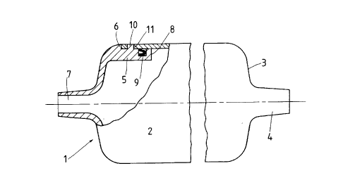
Figure l is a part sectional view of a debris trap
including a reduced pressure seal,


Figure 2 a similar view to Figure l including a
perforated basket in the trap and


Fgiure 3 is a part sectional view of the seal in a
pump debris trap.


DETAILED DESCRIPTION OF THE DRAWINGS


Referring to Figure l the debris trap l consists of a
hollow circular cylindrical body 2 having one end 3
closed and provided with an axial outlet in the form of
a hollow spigot 4 suitable for insertion into a
coupling member of a swimming pool filter suction hose.
The body is made from suitable plastics material.


The other end of the body 2 is formed as a spigot 5
which fits into the end of the body 2 and carries a
radially outwardly extending peripheral flange 6 which
locates against the end of the wall of the body 2.


201~551
_ - 7 -


The spigot 5 has a similar hollow axial inlet opening 7
to that described as the outlet from the body.


The spigot 5 has a peripheral groove 8 formed in the
wall thereof and the groove 8 houses a flexible lip
seal 9. The lips of the seal 9 face the flange 6.


A pintle lO is provided at one part of the periphery of
spigot 5 and this co-operates with a bayonet-type joint
slot ll to enable the spigot 5 to be retained in the
end of the body 2. The spigot S is made to a size so
that the seal 9 will lightly frictionally engage
against the inner surface of the wall of the body.


Thus the spigot 5 forms a removable end to the assembly
and is inserted into the body with the pintle lO
engaging in the slot ll and twisted through a small
angle to retain it in position.


In use the trap is simply connected into the suction

hose for the pool cleaner. When the filter unit is


2013~1
- 8 -


operating large and heavy debris passing through the
hose will fall to the lower level of the trap because
of the reduced flow velocity through the trap. The
suction will result in external pressure opening the
lip seal to seal the removable end in the body.


Figure 2 illustrates the trap of Figure 1 including an
additional component.


The inlet end of the trap has an inwardly directed
circular flange 12 projecting co-axially into the body
and spaced a predetermined distance inwardly of the
longitudinal wall of the body.


A basket 13 of plastics material is provided and the
side wall and bottom 14 of the basket are perforated to
provide a coarse filter for water passing therethrough.


At the outlet end of the body spaced resilient stops 15
are provided and arranged so that when the basket 13 is

located in the body with the bottom 14 on the stops 15
the open end of the basket will be located around the
flange 12 and in substantial contact with the inside of
the inlet end to the body.

~ 2013~51
g

The stops 15 are also such that they will locate the
basket centrally in the body.


The perforations are made such that the openings
through each consecutive 10 per cent of the length of
the basket is greater than the inlet or outlet
openings to the body.


In use the trap is located in the length of the
flexible hose leading from the surface of a swimming
pool to a pool filter for cleaning that surface. Debris
entrained in the water flow to the filter will be
retained in the body of the trap. As the volume of this
debris increases the basket will become filled
therewith and the level of collection of debris in the
basket will be clearly visible from outside.


This will enable a person to decide when the trap is to
be emptied.


Should the trap not be emptied at an appropriate time,
the basket will become full and flow through the trap

seriously impeded. At such a stage the suction acting
through the trap will pull the basket against the


20135Sl
-- 10 --
-
resilient stops 15 to release the open end of the
basket from the inlet end of the body and create a flow
path for unfiltered water through the body between the
outer wall of the basket and inner wall of the body.


This will prevent a choked basket from causing a
serious restriction in flow to the filter and possibly
serious damage to the filter pump.


When the basket is cleared and replaced the stops 15

will re-locate the basket for proper normal filtering
operation.


The use of the debris trap will protect the weir and
pump traps from choking and is more readily cleared
- than the other traps.


Alternatively the open end of the basket need not seat
firmly against the flange 12 but clearance space may be
provided at all time for a by-pass flow outside the
basket. Flow through this by-pass will only take place

when there is a severe restriction to flow through the
perforations in the bottom and walls of the basket.


201~51

.~

The invention as applied to the leaf trap assembly of
a domestic swimming pool filtration pump is illustrated
in Figure 3.


As shown the housing 16 for a leaf trap 17 is fitted
with a closure member 18. This member 18 has a spigot
19 which projects into the housing 16.


Studs 20 secured in the wall of the housing 16 extend
through holes provided in the closure member 18 so that
the latter can be secured against the housing 16 by
means of suitable manually rotateable nuts 21.


A peripheral groove 22 is provided in the wall of the
housing adjacent to the spigot 19 on the closure
member. In this groove 22 is located a lip seal 23. The
lips of seal 23 are directed outwardly towards the
opening in the housing 16 as indicated in the detail of
the drawing.


In use, as soon as reduced pressure is applied within

the housing 16, the lips of seal 23 spread into
effective sealing engagement between the wall of the
groove 22 and the spigot 19 on the closùre member. No
other force is required to effect sealing and the
closure member need not be firmly secured as is
necessary where 0-ring type seals are used.


Dessin représentatif
Une figure unique qui représente un dessin illustrant l'invention.
États administratifs

Pour une meilleure compréhension de l'état de la demande ou brevet qui figure sur cette page, la rubrique Mise en garde , et les descriptions de Brevet , États administratifs , Taxes périodiques et Historique des paiements devraient être consultées.

États administratifs

Titre Date
Date de délivrance prévu 1998-06-23
(22) Dépôt 1990-03-30
(41) Mise à la disponibilité du public 1990-09-30
Requête d'examen 1991-12-19
(45) Délivré 1998-06-23
Réputé périmé 2003-03-31

Historique d'abandonnement

Il n'y a pas d'historique d'abandonnement

Historique des paiements

Type de taxes Anniversaire Échéance Montant payé Date payée
Le dépôt d'une demande de brevet 0,00 $ 1990-03-30
Enregistrement de documents 0,00 $ 1990-12-07
Taxe de maintien en état - Demande - nouvelle loi 2 1992-03-30 100,00 $ 1991-12-19
Taxe de maintien en état - Demande - nouvelle loi 3 1993-03-30 100,00 $ 1993-03-15
Taxe de maintien en état - Demande - nouvelle loi 4 1994-03-30 100,00 $ 1994-03-23
Taxe de maintien en état - Demande - nouvelle loi 5 1995-03-30 150,00 $ 1995-02-16
Enregistrement de documents 0,00 $ 1995-08-17
Taxe de maintien en état - Demande - nouvelle loi 6 1996-04-01 75,00 $ 1996-03-13
Taxe de maintien en état - Demande - nouvelle loi 7 1997-04-01 150,00 $ 1997-02-13
Taxe finale 300,00 $ 1998-02-12
Taxe de maintien en état - Demande - nouvelle loi 8 1998-03-30 150,00 $ 1998-03-24
Taxe de maintien en état - brevet - nouvelle loi 9 1999-03-30 150,00 $ 1999-03-17
Enregistrement de documents 50,00 $ 1999-11-30
Taxe de maintien en état - brevet - nouvelle loi 10 2000-03-30 200,00 $ 2000-03-02
Taxe de maintien en état - brevet - nouvelle loi 11 2001-03-30 200,00 $ 2001-03-05
Titulaires au dossier

Les titulaires actuels et antérieures au dossier sont affichés en ordre alphabétique.

Titulaires actuels au dossier
ZODIAC POOL CARE, INC.
Titulaires antérieures au dossier
BARACUDA INTERNATIONAL, INC.
HELGE JOCHEN SCHNEIDER
KALLENBACH, DIETER H. F.
ZARINA HOLDING C.V.
Les propriétaires antérieurs qui ne figurent pas dans la liste des « Propriétaires au dossier » apparaîtront dans d'autres documents au dossier.
Documents

Pour visionner les fichiers sélectionnés, entrer le code reCAPTCHA :


Pour visualiser une image, cliquer sur un lien dans la colonne description du document. Pour télécharger l'image (les images), cliquer l'une ou plusieurs cases à cocher dans la première colonne et ensuite cliquer sur le bouton "Télécharger sélection en format PDF (archive Zip)" ou le bouton "Télécharger sélection (en un fichier PDF fusionné)".

Liste des documents de brevet publiés et non publiés sur la BDBC .

Si vous avez des difficultés à accéder au contenu, veuillez communiquer avec le Centre de services à la clientèle au 1-866-997-1936, ou envoyer un courriel au Centre de service à la clientèle de l'OPIC.


Description du
Document 
Date
(yyyy-mm-dd) 
Nombre de pages   Taille de l'image (Ko) 
Abrégé 1994-04-01 1 20
Page couverture 1994-04-01 1 24
Revendications 1994-04-01 3 62
Dessins 1994-04-01 3 78
Description 1994-04-01 10 273
Description 1997-10-01 11 275
Revendications 1997-10-01 2 63
Dessins 1997-10-01 3 56
Revendications 1998-05-22 2 63
Description 1998-05-22 11 275
Page couverture 1998-06-19 1 37
Dessins représentatifs 1998-06-19 1 5
Cession 1999-11-30 4 189
Correspondance 1998-02-12 2 43
Lettre du bureau 1991-02-06 1 21
Correspondance de la poursuite 1991-12-19 1 48
Lettre du bureau 1992-03-20 1 36
Correspondance reliée au PCT 1990-07-16 2 100
Correspondance de la poursuite 1997-04-23 8 210
Demande d'examen 1996-11-12 2 115
Correspondance reliée au PCT 1996-08-21 1 43
Taxes 1997-02-13 1 57
Taxes 1996-03-13 1 54
Taxes 1996-08-21 1 45
Taxes 1995-02-16 1 61
Taxes 1993-03-15 1 48
Taxes 1991-12-19 1 51
Correspondance 1996-04-04 1 24
Taxes 1994-03-23 1 60