Note : Les descriptions sont présentées dans la langue officielle dans laquelle elles ont été soumises.
~ .
1 30-CF-l025
METHOD FOR INPUT OUTPUT CONFIGURATION
IN A PROGRAMMABLE LOCIC CONTROLLER
BACKGROUND OF THE INVENTION
This invention relates in general to programmable
logic controllers and, more particularly, to a method
for confi~uring a pro~rammable loeic controller.
Programmable logic contr~llers (PLC's) are a
relatively recent development in process control
technology. As a part of process control, a
pro~rammable logic controller i5 used to monitor input
signals from a variety of input sensors which report
events and conditions occurring in a controlled
process. For example, a PLC can monitor such input
conditions as temperature, pressure, volumetric flow,
and the like. A control program is stored in a memory
within the PLC to instruct the PLC what actions to
take upon encounterin~ parti~ular input si~nals or
conditions. In response to tnese input signals, the
PLC derives and generates output si~nals which are
transmitted to various output de~ices to con~rol the
process. For example, the PLC issues output si~nals
to open or close a relay, rais~ or lower temperature,
adjust pressure, or control the speed of a conveyer,
as well as many other control functions.
~,: ` . ' ' ' ' ' ' ' . `. , ~ ': ' ': :
3~
30GF-1025
- 2 --
The more complex the controlled process, the more
input and output devices (I/0 points) there are likely
to be. Correspondingly, as the complexity of the
controlled process increases, the PLC will likely have
to dedicate more I10 points to the controlled process.
PLC system memory is consumed by such dedicated I/0
points because an address in main memory is generally
set aside for each I/0 point which is defined. Thus
the greater the number of I/0 points associated with a
particular process, the greater is the consumption of
valuable PLC system memory.
Some conventional PLC systems determine the I/0
requirements of the system with respect to a
particular controlled process by examinin~ the control
point references in the control program for that
particular process. In such systems, the PLC will
halt the execution of the control program if it is
determined that there are not enough I/0 points
available to satisfy the needs of the control program.
Unfortunately, in this approach, the maximum number of
available I/0 points is dedicated to a particular
control program since, until the control program is
executed, it is not known how many I/0 points or
addresses will actually be required. In this system,
valuable main memory may be dedicated to I/0 points
which will actually not be used or needed by the
control program. This unfortunately means that it is
likely that some valuable system memory, which will
not actually be used for IlO points, is nevertheless
3n assigned to and dedicated to such purposes and is thus
not available for assignment to other functions.
:. . . .
. ~ .. .
:;
~ :
~ 3 &~
3OGF-1025
- 3
S MMARY OF THE INVENTION
Accordingly, one object of the present invention
is to provide a method for configuring a programmable
logic controller in a manner which conserves valuable
system memory.
Another object the present invention is to provide
a method of configuring a programmable logic
controller in which the user's control over the I10
configuration is enhanced.
In accordance with the present invention, a method
is provided for configuring a pro~rammable logic
controller which is connectable to a plurality of
input devices and output devices. The controller
employed in the method includes a memory and is
capable of executing a control program to control a
process. The method includes the steps of providin~
configuration information with respect to the
confi~uration of the input devices and output devices
to the controller prior to the controller executing
the control program. The method further includes the
step of the controller executing the control program
sub~equent to the providing configuration information
step. In one embodiment, the method includes the
step of assigning address space in the memory to the
input and output devices specified in the
configuration information of the providing step, any
memory space not assigned bein~ designated non-
assigned memory space. This non-assi~ned memory space
i5 advanta~eously released for other controller
operations.
In accordance with another embodiment of the
method of the invention, a method is provided for
configuring a programmable lo~ic controller which is
connectable to a plurality of input devices and output
~J ~
30GF 1025
-- 4 --
devices, the controller including a memory and being
capable of executing a control program to control a
process. This method includes the steps of providing
configuration information with respect to the
configuration of the input and output devices to the
controller prior to the controller executing the
control program. such configuration information being
designated provided configuration information. The
method further includes the steps of determinin~ the
actual configuration of the input and output devices,
and comparing the actual configuration to the provided
configuration information. The method also includes
the steps of the controller performing a first action
if the actual configuration matches the provided
configuration information, and the controller
performing a second action if the actual confi~uration
fails to match the provided configuration information.
BRIEF DESCRIPTION OF THE DRAWINGS
The features of the invention believed to be novel
are specifically set forth in the appended claims.
However, the method of operation of the present
invention may best be understood by referring to the
following description and accompanying drawings in
which:
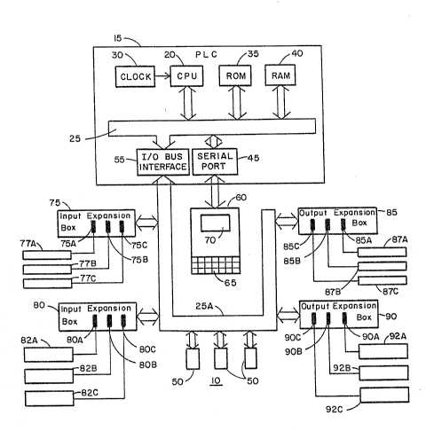
FIG. l is a block diagram of a programmable logic
controller on which the method of the present
invention may be executed; and
FIG. 2 is a flowchart detailing the steps employed
in the method of the present invention.
,~
~ .
.: ., ,; :
2`~
3OGF-1025
-- 5 --
DETAILED DESCRIPT~ON OF THE INVENTION
FIG. Z shows a block diagram representation of a
programmable logic controller system lO on which the
method of the invention may be practiced. System lO
includes a programmable logic controller (PLC) 15
including a central processin~ unit ~CPU) 20 coupled
to a main bus 25. A clock 30 is coupled to CPU 20 to
provide a time base thereto. A read only memory (ROM)
35 is coupled to main bus 25 to provide CPU 20 with
permanent storage in the conventional fashion. A
random access memory (RAM) 40 is coupled to main bus
25 to provide memory space for CPU 20 to conduct PLC
operations and store user programs.
A handheld pro~rammer 60 such as the Series 90-30
hand-held programmer (HHP) manufactured by CE Fanuc
Automation N.A., Inc. is coupled to the PLC by a
serial port 45 to enable the user to input information
into PLC-15. Programmer 60 includes a keyboard 65 on
which the user types input information and further
includes a small display 70 to permit the user to view
the input information while the input information is
bein~ keyed into keyboard 65.
A plurality of input and output ports are coupled
to a bus 25A which is connected to main bus 25 of PLC
15 by I/O bus interface 55. One or more input
expansion boxes such as input expansion boxes 75 and
80 allow multiple input ports to be coupled to main
bus 25 as shown in FIG. l. More specifically,
expansion box 75 includes a plurality of input ports
in the form of bus connector slots (not shown) for
receiving respective input c~rds 75A, 75B and 75C
therein, each card having a port address associated
therewith. Although for purooses of illustration.
input expansion box 75 is shown as including three
~ , . :
.
~ ' i
30GF-1025
-- 6 -
input cards 75A, 75B and 75C, in actual practice box
75 could accommodate more input cards by employing
expansion boxes with more slots (input ports) than
shown. In addition, expansion boxes can also hold
output modules and output modules can incorporate
expansion boxes. I/0 modules 50 may also attach
directly to processor I/0 bus 25. Each of input cards
75A, 75B and 75C is coupled to a respective input
circuit 77A, 77B and 77C. Input circuits 77A, 77B and
77C sense respective conditions and generate input
signals which are reported to the input cards
respectively coupled thereto. The actual input points
monitored by a control program in PLC 15 are located
at these input circuits 77A, 77B and 77C, respectively
or are coupled thereto.
In a fashion similar to expansion box 75,
expansion box 80 includes a plurality of inputs or
slots into which input cards 80A, 808 and 80C are
pluggable. A plurality of input circuits 82A, 82B and
82C are coupled to input cards 80A, 80B and 80C,
respectively, such that information sensed at the
respective input points associated with input circuits
80A, 80B and 80C is provided to input cards 80A, 808
and 80C for transmission to and processing by PLC 15.
A plurality of output ports are coupled to main
bus 25 of PLC 15 (through bus 25A and I/0 interface
55) via one or more output expansion boxes such as
output expansion boxes 85 and 90 which are coupled to
main bus 25. That is, in a manner similar to that of
input expansion box 75, output expansion box 85
includes a plurality of output ports in the form of
bus connector slots (not shown~ for receivin~
respective output cards 85A, 85B and 85C therein, each
output card having a respective port address
associated therewith. Although for example purposes.
` . : ' ' , : ,, . . , . , .:. : - '
., ", :. ,, ,: , ;,. " :,
:
,. ~ .. . . .
: . , .,~ . .
. ~ : , . i , : , . : -:
. -
: . ~:.. . .
2,
30GF-1025
-- 7 --
output expansion box 85 is shown as including three
output cards 85A, 85B and 85C, in actual practice
output expansion boxes 85 may include a greater number
of slots to accommodate a correspondingly greater
number of output cards. Each of output cards 85A, 85B
and 85C produces a respective output control signal
which is processed by an output circuit and then used
to control or drive a particular device. More
specifically, each of output cards 85A, 85B and 85C is
coupled to a respective output circuit 87A, 87B and
87C. Output circuits 87A, 87B and 87C may be
alternatively referred to as amplifiers or device
drivers which amplify the level of the output control
signals provide thereto up to a level sufficient to
drive the particular controlled device (not shown~
coupled to the output circuit. The actual output
points controlled by th2 control program in PLC 15 ar~
located at these output circuits 87A, 87B and 87C,
respectively, or are coupled thereto.
In a manner similar to output expansion box 85,
output expansion box 80 includes a plurality of
outputs or slots into which output cards 90A, 90B and
90C are plug~able. A plurality of output circuits
92A, 92B and 92C are coupled to output cards 90h, 90B
and 90C, respectively, such that the control si~nals
associated with output circuits 90A, 90B and 30C are
provided to output cards 90A, 90B and 90C to
facilitate control of the devices coupled to the
output points associated with such output circuits~
It will be recalled from the earlier discussion
that a control program is provided to PLC 15 to
control the operation of the PLC with respect to a
particular controlled process. PLC 15 is not limited
to executing a particular control program. Rather,
different control programs may be loaded at different
;; ,
, . -
-, :
"'' , ' "
30GF-1025 ~3q~ 3
-- 8 --
times into PLC 15 to enable PLC 15 to monitor various
input points and to issue output control signals to
various output points to permit control of different
controlled processes.
In the method of the present invention. a user
supplied configuration file is provided to PLC 15
prior to the time at which PLC 15 executes the
particular control program provided thereto at RAM 40.
This user supplied configuration file contains
information as to how many input points and output
points are provided by the cards which are presently
mounted in the slots in the input and output expansion
boxes coupled to main bus 25 and also provides
information that ties references in a control program
to physical I/0 points. This configuration file may
be supplied by the user in at least two different
ways.
In one embodiment of the invention, PLC 15 causes
display 55 to present the user with a series of
questions prior to running the particular process
control program stored ;n RAM 40. The user types in
the appropriate configuration information on hand held
programmer 60. More specifically, PLC 15 prompts the
user to key in the number of I10 points (input points
and output points) which are associated with the cards
which are plugged into the slots in input expansion
boxes 75 and 80 and output expansion boxes 85 and 90.
The user is also prompted to supply information
indicating in which expansion box slots the cards are
installed. Additionally, the user is prompted to key
in information which indicates which I/0 references
(input addresses and output addresses) are to be
assigned to the particular input points and output
points. The above described configuration information
." , , : . . , ,,, .:: ,
`: ' ,: '': :~: : :
: ~ . , ' ' ' ; ' ~ ~ :'.
; ::, , - .:: '
30GF-1025
is collected into a configuration file which is stored
in RAM 40 for later reference by PLC 15.
After the user supplied confi~uration information
is provided to PLC 15, PLC 15 configures I/0 points
accordin~ to the requests of the user in the user
supplied configuration information. That is, PLC 15
assigns I/0 points and I/0 point addresses according
to the number of I10 points, slot locations and I/0
point addresses specified in the user supplied
confi~uration information. PLC 15 then performs a
test to determine if the user supplied configuration
information matches the actual hardware configuration
present in programmable logic controller system 10.
For example, a test is made to determine if the actual
hardware configuration contains a sufficient number of
I/0 points to supply the I/0 points requested by the
user in the configuration file. If not, a mismatch
condition exists. A test is made to determine if each
of the I/0 points requested in the user supplied
configuration file is actually present in the physical
hardware arrangement of PLC system 10. If not a
mismatch condition exists.
When PLC 15 prompts the user for configuration
information, it also queries the user to indicate a
2S desired state for a fault flag FF. If fault flag FF
is set to 0, this indicates to PLC 15 that in the
event of a mismatch between the user supplied
configuration information and the actual hardware
configuration wherein a particular I/0 point specified
by the user is not available in the actual hardware
configuration, then this will be considered a fatal
fault by PLC 15. In this event, execution of the
particular control pro~ram in PLC 15 will halt.
However, if fault fla~ FF is set to l, then this
indicates to PLC 15 that this mismatch is not a fatal
", ,",., ":... .
.: "
. . : ''~
: - ; . ~ . . : .-. ,:
~ 30GF-1025 2~
- 10 -
fault and that execution of the control program should
continue except that PLC 15 should provide dia~nostic
information. That is. PLC 15 store an error message
in RAM 40 to indicate that a mismatch occurred between
the user supplied configuration file and the actual
hardware configuration of PLC system 10. The user
program can take a user defined action on this error
condition.
In the present invention, any I/0 points which are
not assigned by the user in the configuration file may
be used for other purposes. For example, any
unassigned output points may be used as internal coils
or storage elements. Advanta~eously, assuming that
not all of the available I/0 points in a partioular
PLC hardware confi~uration are assigned in a
confi~uration file, then a portion of RAM 40 need not
be assign~d to such non-assigned I/0 points. Valuable
system RAM is thus conserved in this manner.
A summary of configuration information which is
provided in the confi~uration file is listed below in
Table 1. The followin~ types of configuration
information are provided for examples purposes. It
should be understood that other configuration
information which describes tha hardware configuration
of PLC 15 could be included as well in the user
supplied configuration information.
... . . .
: ~ ~ , ~ . . . .
. .: : ;: ~ . .;
30GF-1025 2~ 3 ~ ~3~
TABLE l
CONFICURATION FILE CONTENTS
PARAMETER I DESCRIPTION
I NI I number of requested input
1 I points ¦ :
_ I I
NO I number of requested output
points
AI(i) I address of each input point
I I requested (i is an index3
1 AO(j~ I address of each output point
requested lj i 5 an index)
¦ PSN I physical slot number of
which each I and O point is
I I associated
Alternatively, rather than havin~ the user input
the confi~uration file from hand held programmer 60,
the configuration file may be stored in a memory
included in the particular module or card to be
plugged into a slot in HHP 60. Each I/O module
contains confi~uration information as well. The
configuration information contained in the module in
at least one embodiment includes the above described
configuration information and also configuration
information such as module type, module identification
. - ~ , ~ , . ......... . .
:
-: - : ,. . . ~
., :, . . ~
-~ 30GF-1025 2 F~ 3
- l2 -
number and the number amount of input points and
output points which the particular module provides.
In another embodiment. only the number of IlO points
the I/0 mudule provides is stored in the module. This
alternative memory storage approach is discussed in
more detail in the copending U.S. patent application
entitled IlO Verification Method, U.S. Serial No. (30-
GF-1025) filed concurrently herewith and assigned to
the instant assignee.
From the above description it will be appreciated
that the user determines the IJ0 requirements
separately from cre tin~ the PLC control program.
These I/0 requirements are provided as configuration
information to the PLC separately from the control
lS program. In this manner, the user is free to use any
unassigned inputs and outputs for other purposes. For
~xample, any ~nas~ign~d outputs m~y b~ usod a~
internal coils or storage elements.
FIG. 2 is a flowchart which depicts the steps in
the method of the present invention. First,
programmable logic controller system lO is powered on
and initialized as in block lO0. Then, a control
program is provided to PLC 15 via hand held programmer
60. A configuration file is provided to PLC 15 at
block llO. The fault flag FF is set to 0 for fatal
fault or l for continueldiagnostics as discussed
earlier as per block l15. The PLC then assigns input
points and output points as indicated by the input
points and output points in the configuration file as
per block 120. Any non-assigned I/0 points are then
released for other uses at decision block 122 and any
non-assigned PLC system memory is released for other
uses in block 124. A test is made at decision block
125 to determine if the actual hardware configuration
of PLC system lO matches the confi~uration requested
, . .
, ~ .- ~ :;
.,. .-. .. ,. ,
,
30GF-1025
- 13 -
in the configuration file. If the requested
configuration indicated by the configuration file
matches the actual configuration, then the control
program is run as per block 130. During the execution
of the control program, PLC 15 continually tests to
see if the above described match exists as indicated
by the return of flow to the decision block 125 from
run block 130. If it is at any time determined that
the configuration requested in the configuration file
does not match the actual hardware configuration, then
a decision is made to determine if a fatal fault has
occurred as per block 135. If a fatal fault has
occurred, namely if fault flag FF = 0, then execution
of the process control program halts as indicated at
block 140. However, if a fatal fault has not
occurred, namely if fault flag FF = 1, then execution
of the control program continues and dia~nostics
information is provided at block 145 as di~cussed
earlier. By setting fault flag FF to 1, a control
pro~ram can be run for diagnostics and testing
purposes even if no input or output devices are
coupled to PLC 15. Appropriate error messages will be
issued by PLC 15, but the control program will run~
The fore~oing has described a method for
confi~uring a programmable lo~ic controller. In
summary, the PLC employed in this method verifies that
the actual IlO hardware configuration of the PLC
matches an I/0 configuration specified by the user
prior to running a control program on the PLC. This
match determination is performed before executing a
PLC control program and is performed continuously
during the execution of the control program.
Depending on whether or not the user has set a fatal
fault flag FF, if a mismatch occurs at any time
between the actual I/0 configuration and the requested
30GF-1025 ~ '3
- 14 -
I/0 configuration, then the PLC either issues a halt
or continues to execute while providing
diagnostic/error messa~e information to the user, In
the disclosed invention, any memory space in the PLC
memory whish is not needed to fill the demands of the
IlO request in the user provided configuration
information remains free for other PLC tasks and
control program tasks. In this manner, the disclosed
method advanta~eously conserves valuable system memory
when a PLC is configured. Moreover, the user's
control over the I/0 confi~uration of the PLC is
substantially enhanced.
While only certain preferred features of the
invention have been shown by way of illustration, many
modifications and changes will occur to those skilled
in the art. It is, therefore, to be understood that
the present claims are intended to cover all such
modificatiors and changes which fall within the true
spirit of the invention.
-. , ,, : . .
~ . , " ' . ' '