Note : Les descriptions sont présentées dans la langue officielle dans laquelle elles ont été soumises.
TITLE OF THE INVENTION 2 0 1 4 8 2 8
BURNER ARRANGEMENT
BACKGROUND OF THE INVENTION
Field of the invention
The invention proceeds from a burner arrangement
having a main feed channel for a fuel-air mixture, said channel
discharging into a combustion chamber. A swirler that is
penetrated by a burner lance and fitted with swirl vanes is
provided in the course of the main feed channel. Exit openings
for the fuel feed discharge into the main feed channel.
Discussion of background
A burner arrangement according to the preamble is
known from a United States Patent No. 4,850,194 issued on July
25, 1989 to Fuglistaller et al. In this burner arrangement,
fuel and air are mixed in a prechamber, and led into a
combustion chamber through a swirler fitted with swirl vanes. A
more intense mixing of fuel and air is achieved by virtue of the
swirler, so that a perfect combustion process with a low degree
of pollution can take place in the combustion chamber. However,
it is possible for instances of ignition of the fuel-air
mixture, which can have a negative effect on the stability of
the burner arrangement, to occur as early as entry into the
swirler.
SUMMARY OF THE INVENTION
Accordingly, one object of this invention is to
provide a novel remedy in this respect. As exemplified in the
claims, the invention achieves the object of creating a burner
arrangement in which it is not possible for any undesired
instances of ignition to occur outside the combustion chamber.
The advantages achieved by the invention are to be
essentially in that emission values can be
A
- 20148~2~
achieved which are equally as good as with a conventional
premixing burner in conjunction with a substantially longer
service life of the burner arrangement, and moreover its
susceptibility to faults is lowered and its availability is
enhanced. An especially advantageous outcome is that because of
the elimination of the premixing chamber the axial extent of the
burner arrangement can be kept comparatively small.
Therefore, in accordance with the present invention,
there is provided a burner arrangement comprising:
a main feed channel for a fuel-air mixture;
a combustion chamber, said feed channel disposed to
discharge into said combustion chamber;
a swirler being disposed at a location along said feed
channel, said swirler having swirl vanes;
a burner lance extending along a longitudinal axis
towards said combustion chamber, said lance extending through
said swirler;
a plurality of nozzle means for directing a fuel feed
in said lance into said main feed channel, said nozzle means
being positioned along said main feed channel such that at least
one nozzle means discharges fuel into a region between
respective neighboring swirl vanes;
each of said swirl vanes having a nose-shaped
extension extending in a direction opposite from said combustion
chamber;
each of said plurality of nozzle means being
positioned to discharge fuel in a region of said nose-shaped
extension of each swirl vane.
Further embodiments of the invention are the subject
matter of the dependent claims.
The invention, its further development and the
advantages which can thereby be attained are explained in more
detail below with reference to the drawing, which represents
only one embodiment.
BRIEF DESCRIPTION OF THE DRAWING
A more complete appreciation of the invention and many
of the attendant advantages thereof will be readily obtained as
the same becomes better understood by reference to the following
2014~2g
- 2a -
detailed description when considered in connection with the
accompanying drawing, wherein a greatly simplified section
through a burner arrangement according to the invention is
shown.
DESCRIPTION OF THE PREFERRED EMBODIMENTS
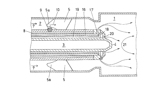
Reference is now made to the only Figure. Discharging
into a combustion chamber 1 is a main feed channel 2, which
conducts a fuel-air mixture into the combustion chamber 1.
Furthermore, the main feed channel 2 surrounds a burner lance 3,
whose head 4 projects a little into the combustion chamber 1.
The burner lance 3 penetrates a swirler having swirl vanes 5
curved in a known way, which is arranged rigidly in the main
feed channel 2. Only the swirl vanes 5 of this swirler are
represented, their mounting having been omitted for the sake of
simplification. Likewise, the combustion chamber 1, the burner
lance 3 and the main feed channel 2 are
..
- 3 - 89/057
represented only in part and greatly simplified.
Arrows 7 specify the direction of inflow of the
air required for the combustion into the main feed
channel 2 and further into the combustion chamber 1. Fuel
is fed in the burner lance 3 through a feed channel 8,
and injected through nozzles 9 into the main feed channel
2, as is indicated by an arrow 10. The nozzles 9 are
arranged such that mixing of the fuel with the air to
form a combustible fuel-air mixture takes place between
the swirl vanes 5. The swirl vanes 5 have noses 5a, which
are drawn forward against the direction of airflow and
channel the airflow. The nozzles 9 are distributed on the
periphery of the burner lance 3 in such a way that at
least one nozzle 9 is provided in each case between two
swirl vanes 5 per interspace.
The Figure will now be considered in more detail
in order to explain the mode of operation. Injection of
the fuel leads to an intense mixing with the air flowing
in the main feed channel 2. Edges projecting into the
flow of the fuel-air mixture can lead to local over-
heating and to undesired instances of ignition of the
mixture outside the combustion chamber 1. If, now, the
fuel is injected in such a way that it is still impos-
sible for any combustible mixture to occur before the
leading edges of the swirl vanes 5 seen in the direction
of flow, a cause of undesired instances of ignition is
thereby removed.
The noses 5a, which are drawn forward against the
direction of airflow and channel the airflow, provide
additional security. It is not possible for mixture to
form, or consequently also for ignition to occur at the
leading edge of the noses 5a. The flow is additionally
accelerated in the region between the swirl vanes 5,
because of the reduction in cross-section which they
cause, so that no possibly occurring combustion could be
stabilized there.
The mixing of fuel and air in the region of the
swirl vanes 5 is sufficient to guarantee good combustion
in the combustion chamber 1, so that only comparatively
..
4 - 89/057
small amounts of pollutants leave the combustion chamber
1. Because of the elimination of the premixing chamber,
the overall length of the burner arrangement is advan
tageously short, so that a comparatively compact arrange
s ment results.
Such a burner arrangement can be provided for
operation with gaseous, liquid or fluidized, powdered
fuel. It is comparatively robust and of low suscepti
bility to wear, and guarantees a high operational availa
bility.
As a rule, the fuel is fed through the burner
lance 3. However, it is perfectly possible for the main
amount of fuel also to be injected between the swirl
vanes 5 through nozzles which are set into the outer wall
of the main feed pipe 2. In this case, the burner lance
3 can be embodied with a smaller outer diameter.
It is advantageous for the nozzle 9 to have a
longitudinal axis which is at a right angle to the
longitudinal axis of the burner lance 3. However, it is
also possible for the longitudinal axis of the nozzle 9
to be inclined. to the combustion chamber 1. In this case,
angles in the range from 90° to approximately 45° to the
longitudinal axis of the burner lance 3 should be
provided. In this way, it is ensured that the fuel-air
mixture cannot arise until between the swirl vanes 5.
On its own, without auxiliary burners, such a
burner arrangement can be controlled only within very
narrow limits . In order to extend the control range of
the burner arrangement, and, in particular, to avoid
complete extinction of the flame in the combustion
chamber 1 when the burner arrangement is idling, the
burner lance 3 has both a back-up burner and a keep-alive
burner. The back-up burner is preferably constructed as
a diffusion burner, and the keep-alive burner as a
premixing burner. Preferably, use is made of a combina-
tion of the two concepts.
Provided in the burner lance 3 to form the back-
up burner is a fuel channel 16 which has exit openings 17
leading radially outwards in the vicinity of the head 4
~~~~a~
- 5 - 89/057
of the burner lance 3.
A premixing chamber 18, into which a channel for
combustion air 19 and the abovementioned fuel channel 16
discharge and which has exit openings 20 oriented axially
towards the combustion chamber 1, is provided in the head
4 of the burner lance 3 to form the keep-alive burner.
The premixing chamber 18 is constructed as an annular
chamber. The exit openings 20 can be distributed evenly
over its circumference, or be constructed as an annular
gap.
The fuel component in the fuel-air mixture
emerging from the exit openings 20 of the premixing
chamber 18 is adjusted such that the mixture is incombus-
tible immediately in front of the head 4 of the burner
lance 3. It cannot ignite until encountering an eddy
return-flow zone 21, which is present in the combustion
chamber 1 and slows it down. As a result, the flame
supported by the keep-alive burner does not form until a
safe distance from the head 4 of the burner lance 3, and
so a flashback of the flame is also reliably prevented,
especially in the premixing chamber 18.
The feed for the fuel and the combustion air for
the back-up burner and the keep-alive burner is prefe-
rably constructed controllably. As a result, the pos-
sibility exists of turning down (partial load) or turning
off (full load) these burners during normal operation of
the burner arrangement, and of not putting them into
operation until required, depending upon the operating
condition of the burner arrangement.
Obviously, numerous modifications and variations
of the present invention are possible in light of the
above teachings. It is therefore to be understood that
within the scope of the appended claims, the invention
may be practiced otherwise than as specifically described
herein.