Note : Les descriptions sont présentées dans la langue officielle dans laquelle elles ont été soumises.
- 1- 2~16260
The present invention relates to a compression
air-conditioning sy~tem for a railroad cax, intended in
;particular for a high-speed train.
In general, a compression air-conditioning system
5of this type chiefly compri~es:
- a compres~or into which a refrigerant is
admitted, compre~sed and expelled under pressure into a
downstream circuit;
- a condenser, connected to the outlet of said
10compressor and in which the refrigerant is cooled by the
air issuing from motor fans, which causes it to liquefy;
- an expansion valve followed by an evaporator,
in which the refrigerant, having been subjected to a
relatively very low pressure, vaporizes, which causes its
15temperature to be lowered and the desired cooling to be
produced;
- a circuit returning the gaseous refrigerant to
the inlet of the compressor after it has passed through
an air-treatment unit in which it is reloaded with heat.
20The air-conditioning system is usually situated
beneath the floor of the car, in a limited space between
this floor, a wall parallel to this floor and lateral and
transverse walls, said lateral walls being provided with
openings for the inlet and outlet of the cooling air.
25The condenser in such a system functions under a
relatively high pressure corresponding to the condensa-
tion pressure of the refrigerant, whereas the evaporator
functions under a relatively low pressure corresponding
to the evaporation pressure of the fluid. The high-pres-
30sure circult i8 connected to the low-pressure circuit, on
the one hand, by the compressor and, on the other hand,
by the expsnsion valve.
Various disadvantages have been noted in trains
equipped with such systemss
35- in certain atmospheric conditions (snow, frost,
~ ... ), it may be observed that the blades of the motor
`',J~ fans ice up, which can cause the entire system to come to
- a standstill, and yet the surrounding cold could enable
the system to function with a reduced number of motor
~"' '~
.,
.
:......................................... . ...
., - . ~ .
: . . : : . ::
:,. - ~ . , . , :: -. . . :
r.
. ' ' ' . ' .. . .
: . . "
-` 2016260
-- 2 --
fan~, or even with no fan~ at all, without risking damage
to the equipment;
- the increase of the heat loads, during a long
period of ~unshine or with a very high number of oc-
cupants, does not enable the desired comfort in terms oftemperature to be ensuxed, given the limitation of the
space available for the air-conditioning system;
- the compressor-condenser unit generates vibra-
tions which are a nuisance, in particular for the comfort
of the passenger6. This disadvantage is further amplified
with the increase in the speed of the trains, which is
desired by rail hauliers, and in view of which the moving
masses are reduced, as this reduction enables higher
speeds to be attained for an equivalent moving force.
Lightening the structures, however, makes them more
sensitive to the vibratory phenomena which are felt by
the passenger magnified at the level of the floor and his
seat, which reduces his level of comfort.
; In this type of system, the reduction of the
vibrations is made difficult by the fact that a refriger-
ating compressor is necessarily connected to the high-
pressure circuit by a rigid pipework which is required by
the nature of the (refrigerant) fluid conveyed and by the
high pressure. The result of this in practice is that the
vibrations of the moving mechanical element which forms
the compressor are transmitted to the whole refrigerating
circuit.
Furthermore, the strict limitation on the space
available for the system makes it impossible for the
conventional shock-absorbing systems to be fitted to it.
In this respect, it should be pointed out that in
existing cars where the system is located in the lower
part of the car, immediately below the body, the tubes of
the condenser in which the refrigerant liquefies are
arranged horizontally between, on the one hand, the floor
of the body and, on the other hand, a plane wall parallel
to this floor and integral with the latter. At their
ends, the tubes are fixed to two vertical parallel plates
in which these ends are regularly distributed.
- .:
.
.. . .
- . ; . :
'
: ~. .. . .
2~16260
Furthermore horizontal plates forming fins are arranged at
regular intervals between the tubes so as to channel the air flow
produced by one or more horizontal-axis fans. The assembly of
the tubes o~ the condenser thus forms one or more banks of tubes,
these banks being traversed by a flow of cooling air.
However, because of the limitation on the available
space, in particular in the vertical direction relative to the
floor of the car, assumed to be horizontal, the cooling capacity
of the system is itself limited, which may have an adverse
effect on the comfort of the passengers.
- The ob~ect of the present invention is to overcome,
at least partially, the ~arious abovementioned disadvantages.
In accordance with the present invention, there is
provided a compression air-conditioning system for a railroad
car, intended in particular for a high-speed train, comprising:
- a refrigerant compressor;
- a condenser comprising tubes in which compressed fluid
is cooled by circulation of air around the tubes and liquefied;
- an expansion valve for supplying a low-temperature
refrigerating gas, said system being situated in a lower part of
the car, beneath a floor of a body of the car, in a space defined
by the floor, a wall substantially parallel to the floor, and
~' lateral walls, said lateral walls being provided with openings for the inlet and outlet of the cooling air;
there being at least one bank of said tubes which is
;j arranged obliquely relative to the floor; and
..;,
, .
-- 3 --
,~
,'' '' ' ~'' ~' '' .,,'."`'''.'.'' '' "' '' ~ '
. .
' ' ` ' ' ' ' ~ ',
-
2016260
wherein some dead spaces thus freed at ends of said
obliquely arranged bank of tubes are used for fitting damping
systems at points where the condenser is fastened to the floor of
the body of the car.
As a result of the oblique arrangement of the banks
of tubes, a high-capacity condenser can be installed in a space
with a reduced height and the cooling capacity of the whole
system can consequently be increased within the same proportions.
Knowing that the lower horizontal wall of the car
must be situated at a minimum height from the track, if
,
'''
, .. .
,...
. - 3a -
;,;- . ,, . , ~ ,- - :
.. - - ,. , ~ : .
201626û
-- 4 --
it i8 desired to increase the vertically available space
for the air-conditioning system, it will be neces~ary to
raise the floor and ultimately the center of gravity and
the height of the cars, with the known unfavorable
S consequences in mechanical, aerodynamic and energy terms.
The invention avoids this need.
The oblique arrangement of the tubes of the
condenser admittedly presents a priori an unfavorable
aspect when taken with the fact that, the flow of cooling
air being substantially horizontal, the flow rate of air
supplied to each unit surface area of the oblique bank is
less than that corresponding to the unit surface area of
the bank which is assumed to be vertical. Calculations
show, however, that the resulting reduction in heat
exchanges may be negligible compared to the rise asso-
ciated with the increase in the transverse dimension of
the bank.
In terms of acoustics, it may be noted that since
the fins ~eparating the tubes are no longer horizontal
and are consequently no longer parallel to the flow of
incident air, they perform the role of baffles for this
flow, which reduces the level of the sound phenomena
associated with this passage of air. This aspect concerns
above all people situated outside the car and near to it:
passengers on the station platforms, car maintenance
staff, ...
- Moreover, it is a priori less easy to connect a
condenser which is oriented obliquely relative to the
substantially horizontal surfaces of the floor and of the
wall arranged beneath this floor, especially if one takes
into consideration the stresses resulting from the
vibrations and ~olts occurring in a car pulled at high
speed.
As a result of a second aspect of the invention,
however, taken with the first aspect consisting in the
obliquenes~ of the condenser, a space is freed in the
vertical direction in the area of the condenser, and some
of the dead zones thus created are used to install shock
damp~s at the points where the condenser is fastened
;'
., .
~.-
- . . .. . .
- -: .
, ~ .
201~2~0
-- 5 --
to the floor of the body of the car.
According to the invention, these dan~ers
preferably consi~t of blocks of resilient materials, for
example rubber, having a vibrating frequency, on the
fundamental or harmonîc level, ~ar apart from the
resonant frequency of the body of the car.
- According to another aspect of the invention,
also aimed at reducing or preventing the transmission of
the vibrations from the air-conditioning system to the
body of the car, the high-pressure circuit comprises, at
the outlet of the compres~or, an expansion trap provided
with a baffle arrangement allowing the circulation of the
lubricating oil, the volume of said expansion trap being
calculated for a vibrating frequency far apart from that
of the body.
According to another aspect of the invention, so
as to prevent, during particular atmospheric circumstan-
ces, the motor fans of the condenser icing up or being
blocked up by snow, and causing the entire air-condition-
ing system to come to a standstill, these motor fans areeach provided with a casing having, in its bottom part,
a heat sensor which, when it detects a temperature which
is close to or below zero, causes the corresponding motor
fan to come to a stand~till. It is, of course, possible
to mount the heat sensors in series 80 that the trig-
gering of one of them causes all the motor fans to come
to a standstill, without causing the remainder of the
air-conditioning system to come to a standstill.
In these conditions of a surrounding low tempera-
ture, it will be pos~ible for the cooling of the conden-
; ser to be sufficient without the help of the flow of
cooling air coming from the motor fans and this will be
all the more 80 since, as a result of the first aspect of
; the invention, the overall cooling capacity being in-
creased, the heat load will be proportionally less great.
, .1
Other features of the invention will emerge from
the description below.
In the attached drawings, given by way of non-
limiting examples:
,: ~
.,
.-:
.. .. . ., ., ~ . . ,.. ,. : .. ..
~016260
-- 6 --
- Figure 1 shows a simplified diagram of an air-
conditioning system for a railroad car, according to the
invention;
- Figure 2 i8 a plan view of the lower part of a
car, the 100r having been removed, showing the general
arrangement of an air-conditioning system according to
the invention;
- Figure 3 is a view in cross-section, on a
larger scale, of an air-conditioning ~y~tem according to
the invention;
- Figure 4 i~ a schematic view of an expansion
trap for an air-conditioning ~ystem according to the
invention.
The functioning of an air-conditioning system
according to the invention will be described at the same
time as the embodiment shown in Figures 1 to 4.
A refrigerant compre~sor 1 (~ee Figure 1) i~
connected to a condenser 2 by a high-pressure duct 3.
The condenser 2 comprises tubes 4 in which the
refrigerant circulates under pressure. The tubes 4 are
cooled by a flow of air, indicated by parallel arrows in
Figure 1, this flow of air being produced by one or more
motor fans 5. The cooling of the refrigerant maintained
: under pressure causes it to liquefy in the condenser 2.
At the outlet of the latter, the refrigerant is brought
.. by the high-pressure duct 3 to an expansion valve 7 in
which it is expanded before passing into an evaporator 8
in which it vaporizes, which causes its temperature to be
lowered considerably. The evaporator 8 is itself situated
in a chamber 9 where the treatment of the air of the car
is performed and which serves, in particular, for ex-
~3 tracting the excess heat from this air by heat exchange
:., with the refrigerant gas. After this heat exchange, the
refrigerant gas returns to the compressor 1.
35 In Figure 1, an expansion trap ~1 according to
:~ the invention (see Figure 4) has also been indicated at
the high-pressure outlet of the compressor 1 and, on
either side of the compressor, two flexible connection-
pipe elements have been shown which are made from a
.,
~ .
2016260
-- 7 --
material enabling them to work in torsion 80 as to be
able to sustain certain ~olts originating from the
compressor, in particular when it is started up.
In Figure 2, th~ relative position of several of
; 5 the main subassemblies of an air-conditioning system
according to the invention has been indicated schem-
atically. ~he flow of air for cooling the refrigerant i8
created by the suction of the fans 5. So as to improve
the overall heat balance, the sucked-in flow of air first
cools the compressor 1 and then passes through the tubes
of the condenser 2.
The transverse arrangement, relative to the car,
of certain subassemblies, as well as of the orientation
of the flow of cooling air, appears more plainly in
Figure 3.
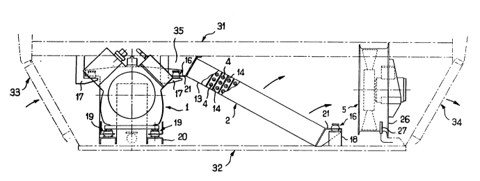
The system i8 placed, in the lower part of the
car, between a floor 31 and a substantially horizontal
wall 32 fastened to this floor by known means, not shown.
The cooling air penetrates through openings in a
lateral wall 33 and exits by openings in a lateral
wall 34 opposite the former.
The condenser 2 comprises a casing 13, connected
tightly to the floor 31 and to the horizontal wall 32, as
well as to the lateral walls 33, 34. In Figure 3, the
casing 13 is shown partially cut away, which allows the
arrangement of the tubes 4 containing the refrigerant to
be seen. These tubes 4 are separated by fins 14 whose
plane surface forms an angle with the incident direction,
3 substantially horizontal, of the flow of cooling air. The
fins 14 thus perform the role of baffles relative to the
flow of incident air and partially reflect the sound
waves propagating with the air, which attenuates the
sound level transmitted to the outside of the car.
It can also be seen in Figure 3 that the inclin-
ation of the banks of tubes forming the condenser 2
enables space to b~ freed in the vertical direction, and
in particular dead spaces such as 35, and shock-absorbing
systems 16 to be posit~oned, resting on supports 17, 18
integral with the walls 31, 32 respectively which are
' ~ .
.
2U1626 0
-- 8 --
themselve~ integral with the body of the car.
- The casing 13 i~ fixed to the dampin~
systems 16 which are here formed by rubber block~, via
flanges 21.
The damperS 16 near the floor 31 also
contribute to damping the vibrations of the compressor 1
by adding their effects to those of dampers 19
placed at the ba~e of the compressor on supports 20
integral with the condenser. A twin suspension i~ thus
formed for the compressor 1 which is significantly more
efficient from the point of view of damping the vibratory
phenomena which originate there.
The expansion trap 11, shown ~chematically in
Figure 4, is connected to the HP outlet of the compres-
sor 1 and is arranged close to the latter. Its volume is
determined 80 as not to transmit frequencies correspond-
ing to the resonant frequency of the body, for example
between 25 and 250 Hz.
The expansion trap 11 is designed so as to enable
the collection and flow-off of droplets of oil from the
lubricating oil of the compressor 1 and which are carried
along by the refrigerant to the outside of the compres-
`l sor. For this purpose, it has a lower wall 23 arranged in
the extension of the lower walls of the inlet conduit and
of the outlet conduit. The trap 11 furthermore has
baffles 22 provided with orlfices 24 which are arranged
such that, near the wall 23, there is no obstacle to the
i circulation of the droplets of oil carried along by the
refrigerant.
In Figure 3, a part of the safety system has been
shown which is intended to bring the motors of the motor
~ fans 5 to a standstill when there is a risk of the blades
- being blocked up due to icing up or due to the accumula-
tion of snow in their clearance space; the system is
designed such that this standstill does not cause the
:
remainder of the air-conditioning system to come to a
,~ standstill.
For this purpose, each motor fan S has a cas-
ing 26, the bottom part of which receives a heat
:~ .
~ , - " -.
,
- 9 - 2 ~J 1 ~26 0
sensor 27 adjustedsoastoprodUCe adisengaging of the motor
fan 5 when the external temperature reaches a value which
i8 close to or below zero degrees without bringing the
remainder of the air-conditioning system to a standstill.
The various heat sensors 27 are preferably mounted in
series in the conventional manner such that the trig-
gering of ~ust one of them causes all the motors of the
fans 5 to come to a standstill but without causing the
remainder of the air-conditioning system to come to a
standstill.
Some numerical data corresponding to an embodi-
ment of an air-conditioning system according to the
invention will be given hereinbelow by way of non-limit-
ing example.
The compressor 1 rotates at 1,500 r/min, which
corresponds to a fundamental frequency of 25 Hz and to
harmonics which may coincide with the resonant frequency
of a railroad car body, generally between 25 and 250 Hz.
The usable height beneath the floor of the car
(between this floor and the underframe of the air-condi-
tioning system) is, for example, 600 mm. The number of
substantially horizontal tubes 4, approximately 1,900 mm
in length, forming a bank of the condenser 2 may be
calculated therefrom. Since the transverse pitch of these
tubes 4 has a standardized value of 25.4 mm, the number
of tubes of a single bank, arranged vertically, is in
practice 22.
~y orienting the condenser 2 obliquely, with an
angle of approximately 30 degrees relative to the
horizontal plane, the available height becomes ~20 mm,
which corresponds in practice to 35 tubes, for a single
bank of tubes, i.e. an increase of more than 50 % as
compared to the 22 tubes of a vertically arranged con-
denser.
Although the flow rate of air per unit surface
area of the bank of tubes is slightly decreased, as the
; value of this flow rate is not critical for the cooling
efficiency of the system, the heat power of the latter
will be increased by approximately 50 ~.
,.
.- ' ' ' - , .
2016~ 0
-- 10 --
Moreover, a~ the speed V of the air close to the
- tubes will be reduced, the head 1088 of the air will be
cub~tantially reduced since it i8 a function of the
square of the speed V, which will further relieve the
work of the motor fans and enable the ventilation noise
conveyed by these motor fans to be reduced.
This advantage is in addi~ion to that given by
the inclination of the fin~ placed between the tubes,
which enables them to play the role of traps for the
sound waves conveyed by the cooling air.
Still as a non-limiting example, in the case of
a condenser inclined such as hereinabove, for a thermo-
dynamic cycle between +8C, the evaporation temperature
of the refrigerant, and +65C, the condensation tempera-
ture of this fluid, the heat powers may be, respectively:
- condenser : 60 kW;
- evaporators 40 kW;
- compressor: 20 kW.
The invention is not, of course, limited to the
exemplary embodiments which have ~ust been described and
`~ numerous modifications may be made to them without going
beyond the scope of this invention.
Instead of an angle of approximately 30 for the
~`~ condenser, a different angle between 25 and 45 could,
;~ 25 for example, be taken.
~oreover, the arrangement of the tubes and of the
fins inside the condenser may be different from that
~, shown in Figure 3.
3 Indeed, the tubes may also be arranged staggered
relative to each other, these tubes being separated from
each other by fins which extend in a direction perpen-
dicular to that of the fins 14 shown in Figure 3.
,~,.
,.:,
:.
:~ .
. .
. '' . . '
- ~ .