Sélection de la langue

Search

Sommaire du brevet 2016724 

Énoncé de désistement de responsabilité concernant l'information provenant de tiers

Une partie des informations de ce site Web a été fournie par des sources externes. Le gouvernement du Canada n'assume aucune responsabilité concernant la précision, l'actualité ou la fiabilité des informations fournies par les sources externes. Les utilisateurs qui désirent employer cette information devraient consulter directement la source des informations. Le contenu fourni par les sources externes n'est pas assujetti aux exigences sur les langues officielles, la protection des renseignements personnels et l'accessibilité.

Disponibilité de l'Abrégé et des Revendications

L'apparition de différences dans le texte et l'image des Revendications et de l'Abrégé dépend du moment auquel le document est publié. Les textes des Revendications et de l'Abrégé sont affichés :

  • lorsque la demande peut être examinée par le public;
  • lorsque le brevet est émis (délivrance).
(12) Brevet: (11) CA 2016724
(54) Titre français: PORTE-OUTIL POUR PLUSIEURS POINCONS
(54) Titre anglais: MULTITOOL PUNCH HOLDER
Statut: Réputé périmé
Données bibliographiques
(52) Classification canadienne des brevets (CCB):
  • 164/136
(51) Classification internationale des brevets (CIB):
  • B26F 1/40 (2006.01)
  • B21D 28/12 (2006.01)
(72) Inventeurs :
  • CHUN, VICTOR L. (Etats-Unis d'Amérique)
  • HUNTER, JAMES R. (Etats-Unis d'Amérique)
(73) Titulaires :
  • MURATA WIEDEMANN, INC. (Etats-Unis d'Amérique)
(71) Demandeurs :
(74) Agent: MACRAE & CO.
(74) Co-agent:
(45) Délivré: 1999-04-27
(22) Date de dépôt: 1990-05-14
(41) Mise à la disponibilité du public: 1990-11-22
Requête d'examen: 1997-03-04
Licence disponible: S.O.
(25) Langue des documents déposés: Anglais

Traité de coopération en matière de brevets (PCT): Non

(30) Données de priorité de la demande:
Numéro de la demande Pays / territoire Date
355,252 Etats-Unis d'Amérique 1989-05-22

Abrégés

Abrégé français

Porte-outil multiple dans lequel un porte-outil (22) porte un ensemble circonférentiel de poinçons (76) dans une série correspondante de centres de travail. Chaque poinçon (76) est fixé à une tige (50) ayant un bout supérieur qui fait saillie au-dessus du porte-outil (22). Le porte-outil (22) est mis en rotation au moyen d'un entraînement à indexage (102, 104 106, 108) de manière à amener une tige choisie (50) sous un dispositif d'entraînement du coulisseau (100) faisant saillie radialement vers l'extérieur pour se trouver au-dessus du bout (52) des tiges. Le porte-outil (22) est couplé au coulisseau (14) par un élément de tête (20) qui y est reçu de façon télescopique, ce qui permet au coulisseau (14) de continuer à descendre après contact du porte-outil (22) avec la pièce à travailler, le coulisseau (14) ayant un dispositif d'entraînement (100) se mettant en prise sur le bout (52) d'une tige choisie se trouvant sous le dispositif d'entraînement du coulisseau (100) pour faire avancer le poinçon fixé (76) contre la résistance d'un ressort extracteur (62) l'encerclant. (FIGURE 1)


Abrégé anglais


A multitool punch holder in which a tool carrier (22)
holds a circumferential array of punches (76) in a
corresponding series of bores. Each punch (76) is attached to
a stem rod (50) having an upper end protruding above the tool
carrier (22). The tool carrier (22) is rotated by an index
drive (102,104, 106, 108) so as to bring a selected one fo the
stem rods (50) beneath a ram drive feature (100) protruding
radially outward to lie above of the stem rod ends (52). The
tool carrier (22) is coupled to the ram (14) by a head member
(20) which is telescopically received therein allowing the ram
(14) to continue its descent after contact of the tool carrier.
(22) with the workpiece, the ram (14) having a feature (100)
engaging a selected stem rod end (52) lying beneath the ram
drive feature (100) to cause advance of the attached punch (76)
against the resistance of an encircling stripper spring (62).
(FIGURE 1)

Revendications

Note : Les revendications sont présentées dans la langue officielle dans laquelle elles ont été soumises.


-8-
CLAIMS

1. A multitool punch holder (10) for a punch press having
a punch support structure comprising a rotary turret plate (12)
and a vertically movable ram (14) for driving a selected punch
(76), said punch holder including a tool carrier (22) mounted
in said rotary turret plate (12) for rotation about an axis,
means coupling said tool carrier (22) to said ram (14) to be
driven thereby, said tool carrier (22) being characterized by a
circumferential array of axially extending bores (48)
distributed about said axis of rotation of said tool carrier
(22), and a plurality of punches (76) each mounted in a
respective one of said plurality of bores (48) in said tool
carrier (22); said tool carrier (22) rotation in said rotary
turret plate (12) enabling indexing of each one of said punches
(76) to an operative position, said means (20, 32) coupling
said tool carrier (22) and said ram (14) including means
producing a limited descending movement of said tool carrier
(22) and punches (76) carried therein together with said ram
(14), said movement of said tool carrier (22) arrested by
contact with a work piece after a predetermined extent of
descending travel of said ram (14), and said means coupling
said ram (14) to said tool carrier (22) enabling continuing
descent of said ram (14) after movement of said tool carrier
(22) is arrested; and, means (100) for driving a single one of
said punches (76) at said operative position by said continued
descent of said ram (14), said selected one of said punches
(76) in an operative position determined by the rotational

-9-
position of said tool carrier (22) in said rotary turret plate
(12).
2. A multitool punch holder (10) for a punch press
according to claim 1 wherein each of said punches (76) are
formed with a punch stem rod (50) having an upper end (52)
protruding above said tool carrier (22), and wherein said ram
(14) is formed with a radial feature (100) aligned with said
single selected punch (76) with said tool carrier (22) in a
given operative position in said turret plate (12).
3. A multitool punch holder (10) for a punch press
according to claim 2 wherein each punch stem rod (50) is urged
upward by an encircling stripper spring (62).
4. A multitool punch holder (10) for a punch press
according to claim 3 wherein said means coupling said ram (16)
and said tool carrier (22) comprises a head member (20) having
a portion (18) engaging said ram (16) and slidably received in
a bore (36) in said tool carrier (22), and a spring (32) acting
between said head member (20) and said tool carrier (22)
resisting relative axial movement therebetween.
5. A multitool punch holder (10) for a punch press
according to claim 4 further including a stripper plate (80)
attached to the lower face of said tool carrier (22) and
adapted to engage said workpiece upon downward strokings of
said ram (14).
6. A multitool punch holder (10) for a punch press
according to claim 1 further including an index sleeve (40)
rotatatably mounted in said punch press punch holder structure

-10-

(12) but restrained against axial movement therein, said tool
carrier (22) axially movable in said index sleeve (40) but
rotationally coupled thereto; and further including indexing
drive means (102, 103) for rotating said index sleeve (40).
7. A multitool punch holder (10) for a punch press
according to claim 6 further including spring plunger means
(98) yieldably restraining said tool carrier (22) in said index
sleeve (40) against axial displacement therefrom.

Description

Note : Les descriptions sont présentées dans la langue officielle dans laquelle elles ont été soumises.

--1--
~0~67


MULTITOOL PUNCH HOI,DER

This invention concerns tool holders and mor particularly
holders for carrying punches in punch presses particularly
punch presses having rotary turrets carrying punches to enable
automated punch changing. There has heretofore been developed
punch presses having upper and lower turret plates respectively
carrying a circumferential array of punches and mating dies
able to be selectively indexed to a punch ram. Thi~ enables
automated changing of punches and dies in the operation of the
punch press.
The punches have also been mounted and driven to enable
indexing about their own axis in order to change the
orientation of the punch for a given punching operation. An
example of such indexed tool holder is described in U.S. Patent
4,412,469 issued on November 1, 1983 for "Turret Punch Presses
Having Tool Holders Rotatably Mounted in the Turrets".
It would greatly increase the number of punches available
if a number of punches were included at each station in the
turret, in a rotary holder itself able to rotate about its own
axis, and such multitool punch holders have heretofore been
proposed. Examples of these are described in U.S. Patent
4,569,267 issued on February 11, 1986 for a "Multitool Punch
Mechanism" and U.S. Patent 4,779,329 issued on October 25, 1988
for a "Tool Changer for Rotatable Tool Assemblies in Punching


,~ . ~., i; . , . ~ ,;

-2- ~016~

Machines".
However, it is important that such punch holders be able
to generate sufficient stripping forces to insure reliable
punching, i.e., to exert punch withdrawl forces after punch
penetration of the workpiece has occurxed.
It is also important that such rotary indexing tool
holders be simple and reliable in operation.

Summary of the Invention
The present invention comprises a multitool punch holder
of the rotary indexing type in which a tool carrier cylinder is
provided mounted in an axially fixed sleeve rotatable about its
axis by an indexing drive.
The tool carrier is formed with a plurality of axial bores
arranged about the carrier rotary axis, each bore adapted to
slidably receive a punch stem rod, each having a punch at the
lower and thereof. Each punch stem is formed with a plunger
portion protruding above the tool carrier and indexable beneath
a protruberance formed on the punch ram so as to be selectively
driven as the ram is reciprocated.
A stripper spring surrounding each punch stem resists
advancing by the ram stroke, and acts as a stripping spring to
withdraw the associated punch after workpiece penetration.
The ram is secured to the tool carrier by a head member
telescoped into the tool carrier, axially movable therein
against the resistance of a compression spring serving to
maintain each punch stem rod below the ram drive feature during
indexing of the tool holder.


. .

-3- Z O ~6
A stripper plate is mounted to the lower face of the tool
carrier, and engages the workpiece as the ram strokes to
initiate driving of a selected stem and punch beneath the ram
drive feature.
This multitool punch holder assembly has the advantage of
providing a multitool selection but of a simple and reliable
configuration, and at the same time generating adequate punch
stripping forces.

Description of the Drawings
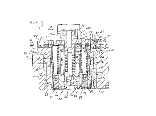
FIGURE 1 is a longitudinal sectional view through a
multitool punch holder according to the present invention, with
a fragmentary portion of associated punch press structure.
FIGURE 2 is an end view of the punch holder shown in
FIGURE 1.

Detailed Description
FIGURES 1 and 2 illustrate the multitool punch holder 10
according to the present invention, shown installed in the
upper turret plate 12 of a rotary turret punch press. The
press ram 14 is formed with a tee slot 16 which received a tee
shaped head 18 of a tee member 20 included in the holder
assembly 10. The tee member 20 is telescopically received into
a cylindrical tool carrier 22 by a mounting rod 24 threaded at
25 into the lower end of tee member 20, having a head 26 seated
against an endwall 28 in a bore 30 formed in the tool carrier
22 slidably receiving the mounting rod 24.
A return compression spring 32 encircles the mounting rod
24 and is seated against endwall 34 of the bore 36 slidably


., ,

_4_ ~ O~ q

receiving the tee member 20. This urges the tool carrier 22
downwardly to be lowered away from the ram 14 prior to
stroking of the ram, as shown in FIGURE 1.
The tool carrier 22 is mounted in an index sleeve 40 so as
to be axially movable therein, but locked against relative
rotation by a key 42 secured to the tool carrier 22 with a
screw 44, and mating with a keyway slot 46 formed in the index
sleeve 40.
The tool carrier 22 is formed with a series of twelve
axial bores 48 spaced radially outward from the centerline of
the tool carrier, in a circumferential array. Each bore 48 is
adapted to receive a punch stem rod 50, extending parallel to
each other, having an upper plunger end 52 guided through a
bronze bushing 54 and protruding above the upper end face of
the tool carrier 22. A retainer plate 56 is secured to the end
face 56 with screws 58, keeps the punch stem rods 50 in
position in the bores 48.
A stripper spring 62 encircles each punch stem rod 50, and
is seated against a thrust washer 64 abutting a shoulder 66 in
the lower section of bore 48 and shoulder 68 of the stem rod
50. The stripper springs 62 also act against a thrust washer
beneath the bronze bushing 54. Downward movement of the
stem rods 50 is resisted by compression of the stripper springs
62 by snap rings 60 acting on thrust washer 72 and bushing 54
and thrust washer 70.
The stem rods 50 each include a threaded section 74
received in a punch 76 alternatively, 76 the stem rods 50 and

-5~ 67,~:~

punches 76 may be made one piece to reduce costs. An
antirotation dowel 78 maintains the orientation of the punch
76~
A urethane stripper end cap B0 is secured with capscrews
82 and dowels 84 to the lower end face 86 of the tool carrier
with punch openings 88 alinged with each punch 76, preferably
formed by the punches themselves in the initial cycle of
operation.
The index sleeve 40 is rotatably received in a bushing
sleeve 90 fixed in the upper turret plate 12 with capscrews 92.
The index sleeve 40 is restrained axially by means of a flange
94 resting on flange 96 o~ the bushing sleeve 90, but free to
rotate. The tool carrier 22 rotates with the index sleeve 40,
but is axially movable therein. A series of spring plunger
assemblies 98 yieldably retains the tool carrier 22 axially
within the index sleeve 40.
The index sleeve 40 is adapted to be rotationally driven
to index each stem rod end 52 beneath an asymetric ram
engagement feature 100 extending radially out ~rom the main
shape of the ram 14 to lie above a single stem rod end 52.
This thereby enables selective punching by ram descending
motion with a single selected punch 78 indexed to that
position.
The rotation of the index sleeve 40 may be carried out by
an index drive arrangement 103 mating with a vee block drive
feature 102 attached to the upper side of flange 94 such index
drive 103 could include a drive wedge axially movable on a
plate to seat in the vee block drive feature 102, the drive


, ;- , ,, . ,, :. ;

-6- ~ 167~'~

wedge driven by a worm to enable rotation to index the tool
carrier 22.
A "home" detent comprised of a spring plunger assembly 110
seats in a pocket 112 in the flange 96 of bushing 90. The
punch holder assembly 10 is located initially by seating of the
spring plunger 110, which prevents unintended movement out of
the home position even if a considerably delay occurs prior to
the initial indexing cycle.
In operation, the turret plate 12 is rotated to engage the
ram 14 with the head member 20.
The indexing drive is activated to bring a selected one of
the stem rod 50 beneath the ram engagement feature 100.
The ram 16 is then stroked, causing tool carrier 22 to
descend with the head member 20 until the stripper plate 80
engages the surface of a workpiece. The head member 20
continues to descend with the ram, telescoping by sliding into
the bore 36 against the resistance of compression spring 32.
The tool carrier 22 heing arrested against any further
axial movement, the ram feature 100 descends to engage the
protruding end 52 of the stem rod 50 located therebelow. This
causes the attached punch 76 to be driven through the workpiece
against the resistance of the encircling stripper spring 62.
As the ram 14 thereafter ascends, the stripper spring 62
forces the stem rod 50 upward to withdraw the attached punch 76
from the workpiece.


. . .

-7- Z ~67~

Continued ascent of the ram 14 raises the tool carrier 22
to the return positon, and draws the head member 20 out of the
bore 36, with the spring 32 holding it in this position after
the ram moves out of engagement with the tee shaped portion 18.


., , , ~
.. . , . - . . . . -

Dessin représentatif
Une figure unique qui représente un dessin illustrant l'invention.
États administratifs

Pour une meilleure compréhension de l'état de la demande ou brevet qui figure sur cette page, la rubrique Mise en garde , et les descriptions de Brevet , États administratifs , Taxes périodiques et Historique des paiements devraient être consultées.

États administratifs

Titre Date
Date de délivrance prévu 1999-04-27
(22) Dépôt 1990-05-14
(41) Mise à la disponibilité du public 1990-11-22
Requête d'examen 1997-03-04
(45) Délivré 1999-04-27
Réputé périmé 2003-05-14

Historique d'abandonnement

Il n'y a pas d'historique d'abandonnement

Historique des paiements

Type de taxes Anniversaire Échéance Montant payé Date payée
Le dépôt d'une demande de brevet 0,00 $ 1990-05-14
Enregistrement de documents 0,00 $ 1991-01-23
Taxe de maintien en état - Demande - nouvelle loi 2 1992-05-14 100,00 $ 1992-05-13
Taxe de maintien en état - Demande - nouvelle loi 3 1993-05-14 100,00 $ 1993-03-08
Taxe de maintien en état - Demande - nouvelle loi 4 1994-05-16 100,00 $ 1994-04-20
Taxe de maintien en état - Demande - nouvelle loi 5 1995-05-15 150,00 $ 1995-03-14
Taxe de maintien en état - Demande - nouvelle loi 6 1996-05-14 150,00 $ 1996-03-11
Taxe de maintien en état - Demande - nouvelle loi 7 1997-05-14 150,00 $ 1997-02-25
Taxe de maintien en état - Demande - nouvelle loi 8 1998-05-14 150,00 $ 1998-04-30
Taxe finale 300,00 $ 1999-01-19
Taxe de maintien en état - brevet - nouvelle loi 9 1999-05-14 150,00 $ 1999-05-14
Taxe de maintien en état - brevet - nouvelle loi 10 2000-05-15 200,00 $ 2000-05-15
Taxe de maintien en état - brevet - nouvelle loi 11 2001-05-14 200,00 $ 2001-03-05
Titulaires au dossier

Les titulaires actuels et antérieures au dossier sont affichés en ordre alphabétique.

Titulaires actuels au dossier
MURATA WIEDEMANN, INC.
Titulaires antérieures au dossier
CHUN, VICTOR L.
HUNTER, JAMES R.
WARNER & SWASEY COMPANY (THE)
Les propriétaires antérieurs qui ne figurent pas dans la liste des « Propriétaires au dossier » apparaîtront dans d'autres documents au dossier.
Documents

Pour visionner les fichiers sélectionnés, entrer le code reCAPTCHA :


Pour visualiser une image, cliquer sur un lien dans la colonne description du document. Pour télécharger l'image (les images), cliquer l'une ou plusieurs cases à cocher dans la première colonne et ensuite cliquer sur le bouton "Télécharger sélection en format PDF (archive Zip)" ou le bouton "Télécharger sélection (en un fichier PDF fusionné)".

Liste des documents de brevet publiés et non publiés sur la BDBC .

Si vous avez des difficultés à accéder au contenu, veuillez communiquer avec le Centre de services à la clientèle au 1-866-997-1936, ou envoyer un courriel au Centre de service à la clientèle de l'OPIC.


Description du
Document 
Date
(yyyy-mm-dd) 
Nombre de pages   Taille de l'image (Ko) 
Page couverture 1993-11-02 1 13
Page couverture 1999-04-20 2 79
Abrégé 1993-11-02 1 25
Revendications 1993-11-02 3 92
Dessins 1993-11-02 1 50
Description 1993-11-02 7 234
Dessins représentatifs 1999-04-20 1 24
Correspondance 1999-01-19 1 28
Lettre du bureau 1990-10-29 1 51
Correspondance reliée au PCT 1991-01-15 1 22
Correspondance de la poursuite 1997-03-04 1 34
Taxes 1997-02-25 1 47
Taxes 1996-03-11 1 63
Taxes 1995-03-14 1 43
Taxes 1994-04-20 1 45
Taxes 1993-03-08 1 37
Taxes 1992-05-13 1 24