Sélection de la langue

Search

Sommaire du brevet 2019897 

Énoncé de désistement de responsabilité concernant l'information provenant de tiers

Une partie des informations de ce site Web a été fournie par des sources externes. Le gouvernement du Canada n'assume aucune responsabilité concernant la précision, l'actualité ou la fiabilité des informations fournies par les sources externes. Les utilisateurs qui désirent employer cette information devraient consulter directement la source des informations. Le contenu fourni par les sources externes n'est pas assujetti aux exigences sur les langues officielles, la protection des renseignements personnels et l'accessibilité.

Disponibilité de l'Abrégé et des Revendications

L'apparition de différences dans le texte et l'image des Revendications et de l'Abrégé dépend du moment auquel le document est publié. Les textes des Revendications et de l'Abrégé sont affichés :

  • lorsque la demande peut être examinée par le public;
  • lorsque le brevet est émis (délivrance).
(12) Brevet: (11) CA 2019897
(54) Titre français: TENDEUR
(54) Titre anglais: TIGHTENER
Statut: Réputé périmé
Données bibliographiques
Abrégés

Abrégé anglais


The tightener comprises a scissor clamp having first
and second arms pivotally connected at their upper ends. At
their lower ends, the arms are pivotally connected with the ends
of a loop of chain that encircles a pair of semi-circular steel
shells encircling a pipeline. The rod of a cylinder is pivotally
connected to move the front arm toward the rear arm. The
cylinder is positioned to operate generally perpendicularly
relative to the arms.

Revendications

Note : Les revendications sont présentées dans la langue officielle dans laquelle elles ont été soumises.


THE EMBODIMENTS OF THE INVENTION IN WHICH AN EXCLUSIVE
PROPERTY OR PRIVILEGE IS CLAIMED ARE DEFINED AS FOLLOWS:

1. In combination:
a pipeline;
a pair of semi-circular shells mounted about the
pipeline; and
a tightener for clamping the shells against the
pipeline, said tightener comprising
a scissor clamp having a pair of arms pivotally
connected at their first ends,
a loop of chain extending around the shells, the ends
of the loop being pivotally connected with the second ends of the
arms, whereby the arms may pull on the loop ends to tighten the
loop about the shells,
a fluid-actuated cylinder, pivotally connected with the
first arm between its ends, for biasing the first arm toward or
away from the second arm, said cylinder being arranged generally
perpendicularly to the arms and being spaced out of contact with
the chain,
said second arm abutting and being supported by the
front end of the cylinder.
2. The combination as set forth in claim 1 wherein:
the cylinder carries a support plate at its front end,
the rear surface of the second arm abuts the front
surface of the support plate, and
the abutting portions of the second arm rear surface
and the front surface of the support plate have mating curved
surfaces.


Description

Note : Les descriptions sont présentées dans la langue officielle dans laquelle elles ont été soumises.

~1989~
1 BACRGROUND OF THE INVENTION
2 In my co-pending Canadian application 2 o o ~ 8 ~1
3 - filed December 6, 1989, I teach a sleeve assembly for
4 repairing a leak in the wall of a steel pipeline for conveying
oil. This assembly involves mounting a pair of semi-circular
6 steel shells around the line and tightening or pressing them into
7 load-applying engagement with the circular pipe wall. One of the
8 shells carries a protruding annular seal member which seats in
9 a recess formed by the inner surface of the shell. The seal
member surrounds the leaking aperture and seals around it to
11 prevent fluid escape between the shell and the pipe. Once the
12 seal member has sealed, the stressed shells are welded
13 longitudinally to create a permanent, full encirclement sleeve.
14 In connection with tightening the shells against the
pipe it is desirable:
16 - That, as much as possible, the load being applied
17 by the tightener be distributed uniformly to the
18 shells. If the load is relatively concentrated
19 at a point, there is a risk of denting the sleeve
and pipe;
21 - That the tightener used be adapted for use with
22 shells and pipe of different curvatures or
23 diameter; and

24 - That the tightener is powered by a fluid cylinder
so that the extent of loading may conveniently be
26 monitored.


2 *

201~897

1 SUMMARY OF THE INVENTION
2 In accordance with the invention, there is provided:
3 - a scissor clamp having arms pivoted at a first end
4 and having means at the second end for engaging
the two ends of a chain loop; and
6 - a fluid-actuated cylinder disposed substantially
7 perpendicularly to the arms when the latter are
8 together, said cylinder carrying a support plate
9 at one end, the rear surface of the clamp's first
arm abutting the support plate, the cylinder being
11 connected to the clamp's second arm between its
12 ends, whereby the cylinder may bias the second arm
13 toward or away from the supported first arm.
14 Preferably the abutting portions of the first arm rear
surface and the support plate front surface have a concave/convex
16 conformance, so that the first arm remains well supported as the
17 clamp arms pivot between open and closed positions with the chain
18 tensioned.
19 The chain can be lengthened or shortened to leave a gap
between its ends, when the chain is taut, which gap is about
21 equal to the spacing between adjacent chain pins. As a result,
22 the radial loading applied against the shells and pipe by the
23 undersurface lobes of the chain is substantially uniformly
24 distributed about the circumference of the sleeve formed by the
shells.

2019897
1 DESCRIPTION OF THE DRAWINGS
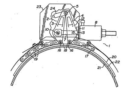
2 Figure 1 is a partly broken away side view of the
3 tightener, comprising a clamp, chain and cylinder, mounted on a
4 shell and pipe assembly with the chain in a tensioned state, some
of the parts being shown in shadow lines;
6 Figure 2 is a simplified rear perspective view of the
7 tightener mounted on the shell and pipe assembly;
8 Figure 3 is a simplified side view showing the clamp
9 in operation; and
Figure 4 is a front view of the front arm of the clamp,
11 showing the clevis, rod and arm pins, and the rod of the
12 cylinder.

13 DESCRIPTION OF THE PREFERRED EMBODIMENT
14 The tightener 1 comprises a clamp 2 having a pair of
jaws or arms 3,4 pivotally connected at their upper ends by a
16 pin 5. Each arm 3,4 is formed to provide a clevis 6 at its lower
17 end. The rod 7 of a fluid-actuated cylinder 8 extends through
18 the rear clevis 6 and is connected at its forward end by a pin
19 10 to the clevis 6 of the forward arm 3 between its ends. The
cylinder 8 carries a support plate 11 at its forward end. The
21 rear surface 12 of the rear arm 4 of the clamp 2 abuts the
22 support plate 11.
23 The rear surface 12 of the rear arm is formed with a
24 convex portion 13 and the front surface 14 of the support plate
11 is formed with a concave portion 15 that conforms with the
26 portion 13. This "knuckle joint" arrangement permits the force
27 from the hydraulic cylinder to be distributed equally and

201~7

1 repeatedly to the clamp arms. This enables the clamp to be used
2 with pipe and shells of different diameters.
3 The cylinder 8 is disposed to act generally
4 perpendicularly relative to the arms 3,4.
At their lowest extremities, the arms 3,4 are each
6 connected by an end pin 16 with one end of a loop 17 of leaf
7 chain. When the loop 17 is just tensioned, the ends 18 of the
8 loop 17 are spaced apart a distance substantially the same as the
9 distance between the lobes 19 of the undersurface of the chain.
Thus the inwardly directed loading of the tightening chain is
11 substantially evenly distributed about the circumference of the
12 shells 20 which are mounted on the pipeline 21. Strips 22 of
13 Teflon* or the like are preferably provided between the shells
14 20 and the pipeline 21, to save the pipeline from scoring by the
chain and to ease the advance of the chain as it is tightened.
16 A lift lug 22 is connected with the upper ends of the
17 arms 3,4 for handling the clamp 2.
18 A safety housing 23 encloses the arms 3,4 in case of
19 breakage.
Conventional means, such as a hand-operated pump (not
21 shown) will be connected with the cylinder 8 to actuate it.
22 The scope of the invention is set forth in the appended
23 claims.


-:- * designates a trade-mark

Dessin représentatif
Une figure unique qui représente un dessin illustrant l'invention.
États administratifs

Pour une meilleure compréhension de l'état de la demande ou brevet qui figure sur cette page, la rubrique Mise en garde , et les descriptions de Brevet , États administratifs , Taxes périodiques et Historique des paiements devraient être consultées.

États administratifs

Titre Date
Date de délivrance prévu 1996-02-06
(22) Dépôt 1990-06-26
Requête d'examen 1991-01-18
(41) Mise à la disponibilité du public 1991-12-26
(45) Délivré 1996-02-06
Réputé périmé 2005-06-27

Historique d'abandonnement

Il n'y a pas d'historique d'abandonnement

Historique des paiements

Type de taxes Anniversaire Échéance Montant payé Date payée
Le dépôt d'une demande de brevet 0,00 $ 1990-06-26
Enregistrement de documents 0,00 $ 1991-04-05
Taxe de maintien en état - Demande - nouvelle loi 2 1992-06-26 100,00 $ 1992-01-06
Taxe de maintien en état - Demande - nouvelle loi 3 1993-06-28 100,00 $ 1993-05-13
Enregistrement de documents 0,00 $ 1994-02-11
Taxe de maintien en état - Demande - nouvelle loi 4 1994-06-27 100,00 $ 1994-05-11
Taxe de maintien en état - Demande - nouvelle loi 5 1995-06-26 150,00 $ 1995-06-26
Taxe de maintien en état - brevet - nouvelle loi 6 1996-06-26 150,00 $ 1996-06-17
Taxe de maintien en état - brevet - nouvelle loi 7 1997-06-26 150,00 $ 1997-06-25
Taxe de maintien en état - brevet - nouvelle loi 8 1998-06-26 150,00 $ 1998-06-24
Taxe de maintien en état - brevet - nouvelle loi 9 1999-06-28 150,00 $ 1999-06-25
Taxe de maintien en état - brevet - nouvelle loi 10 2000-06-26 200,00 $ 2000-05-16
Taxe de maintien en état - brevet - nouvelle loi 11 2001-06-26 200,00 $ 2001-06-19
Enregistrement de documents 50,00 $ 2001-11-27
Taxe de maintien en état - brevet - nouvelle loi 12 2002-06-26 200,00 $ 2002-05-06
Taxe de maintien en état - brevet - nouvelle loi 13 2003-06-26 200,00 $ 2003-05-05
Titulaires au dossier

Les titulaires actuels et antérieures au dossier sont affichés en ordre alphabétique.

Titulaires actuels au dossier
ENBRIDGE PIPELINES INC./PIPELINES ENBRIDGE INC.
Titulaires antérieures au dossier
INTERHOME ENERGY INC.
INTERPROVINCIAL PIPE LINE COMPANY A DIVISION OF INTERHOME ENERGY
INTERPROVINCIAL PIPE LINE INC.
INTERPROVINCIAL PIPE LINE LIMITED
SAVARD, DONALD D.
Les propriétaires antérieurs qui ne figurent pas dans la liste des « Propriétaires au dossier » apparaîtront dans d'autres documents au dossier.
Documents

Pour visionner les fichiers sélectionnés, entrer le code reCAPTCHA :


Pour visualiser une image, cliquer sur un lien dans la colonne description du document. Pour télécharger l'image (les images), cliquer l'une ou plusieurs cases à cocher dans la première colonne et ensuite cliquer sur le bouton "Télécharger sélection en format PDF (archive Zip)" ou le bouton "Télécharger sélection (en un fichier PDF fusionné)".

Liste des documents de brevet publiés et non publiés sur la BDBC .

Si vous avez des difficultés à accéder au contenu, veuillez communiquer avec le Centre de services à la clientèle au 1-866-997-1936, ou envoyer un courriel au Centre de service à la clientèle de l'OPIC.


Description du
Document 
Date
(yyyy-mm-dd) 
Nombre de pages   Taille de l'image (Ko) 
Description 1996-02-06 4 140
Page couverture 1996-02-06 1 15
Abrégé 1996-02-06 1 15
Revendications 1996-02-06 1 34
Dessins 1996-02-06 4 101
Page couverture 1993-12-04 1 15
Abrégé 1993-12-04 1 14
Revendications 1993-12-04 1 35
Dessins 1993-12-04 3 70
Description 1993-12-04 4 145
Dessins représentatifs 1999-07-15 1 13
Taxes 1997-06-25 1 39
Taxes 2003-05-05 1 37
Taxes 2001-06-19 1 40
Correspondance 2001-11-14 4 93
Cession 2001-11-27 6 203
Correspondance 2002-01-15 6 153
Taxes 2002-05-06 1 40
Taxes 1998-06-24 1 33
Taxes 1999-06-25 1 31
Taxes 2000-05-16 1 34
Correspondance reliée au PCT 1995-11-29 1 41
Lettre du bureau 1991-03-07 1 21
Correspondance de la poursuite 1995-06-30 1 31
Taxes 1996-06-17 1 28
Taxes 1995-06-26 1 30
Taxes 1994-05-11 1 29
Taxes 1993-05-12 1 24
Taxes 1992-01-06 1 32