Note : Les descriptions sont présentées dans la langue officielle dans laquelle elles ont été soumises.
2~~1~~6
EXPANDED CABLE JOINT ELASTIC SLEEVES wITH
PERMISSIBLE RESIDUAL DEFORMATION AFTER STORAGE
BACKGROUND OF THE INVENTION
Field _of the Invention
The present invention relates to a sleeve fox covering cable
joints and which are made of compounds of cross-linked polymeric
material, to be applied to several different cables having
different outer diameters.
Prior Art Description
In order to provide a junction between electrical cable
lengths which carry electrical energy, particularly in the field
of medium and high voltages, the layers around the cable
conductors are stripped off stepwise at the ends, that is, the
conductors are devoid of the respective insulating layers and, if
present, semiconductive layers, for the purpose of exposing the
conductors thereby allowing their mutual connection and
subsequently, the zone without the insulating layer is filled with
appropriate materials and then covered with an outer layer or
sleeve so as to restore the required insulating characteristics
in the junction area.
For such purposes, a tubular element, hereinafter referred
to as a sleeve, is fitted over the junction area. The sleeve is
made of cross-linked polymeric material consisting of several
layers each having specific electrical features, and as a whole,
it is designed to be elastically clamped around the surface of
the insulating layer of the connected cables.
The sleeve is radially expanded and maintained under
expanded conditions until the moment of use. after the sleeve
has been put over the junction area its shrinkage around the
surface of the cable insulating layer is carried out thereby
exerting a pressure thereon capable of ensuring the necessary
1
CA 02021956 2000-02-10
77909-39
electrical requirements.
In order to keep the sleeve under expanded
conditions, it can be made of thermoshrinkable material, a
material which is capable of maintaining the expansion it has
received until it is shrunk by the application of heat.
However, this technique requires delicate operations for the
installation of the sleeve because heating means such as open
flames are needed to carry out the thermoshrinkage of the
sleeve.
Alternatively, the sleeve may be made of an elastic
material and fitted around a tubular support body which is
removed by known techniques after the sleeve has been brought
to the intended position which enables the sleeve to
elastically shrink and clamp the cable insulating layer.
For such purposes, elastic multilayered sleeves have
been made, each layer being of small thickness and being
elastically expanded and independently supported on respective
tubular bodies, such layer being applied one after the other
until the intended thickness has been reached. In this way,
each layer is submitted to the minimum permissible expansion,
but several contact areas are created between the different
separate layers which increases the risk that polluting
substances or air bubbles may be incorporated. Consequently,
the phenomena of partial discharges may arise which cause a
joint failure in a short time.
Also, sleeves of great thickness have been made as
disclosed, for example, in Canadian Patent No. 2,007,738 filed
January 15, 1990 and issued April 23, 1996, assigned to the
assignee of the present application and entitled "Multi-Layer
Elastic Sleeves for Electric Power Cable Joints and Joints
2
CA 02021956 2000-02-10
77909-39
Therewith", in which in particular provision is made for a
sleeve of a single size for covering cable junctions having
different sizes by the use of sleeves disposed in the
elastically expanded state on the respective supports at the
factory and kept as such until the
2a
moment of their installation.
With the sleeve of said patent application, the problem of
imparting to the sleeve an expansion sufficient to enable it to
be fitted over the cable having the largest diameter in the group
of the intended sizes while at the same time enabling the sleeve
to be efficiently clamped also around the cables of the smallest
size in the group has been solved by the use, for the outermost
layer of the sleeve, of a material having a reduced residual
deformation when the applied expansion stress has ceased.
Therefore, the sleeve is adapted to allow the whole sleeve to be
clamped around the small-sized cables in an efficient manner.
In fact, the polymeric materials to be used for the
manufacture of sleeves in which each layer needs particular
electrical features, well known in the field, generally have an
elastic return to the original size which is incomplete, th at is,
the sleeve has a temporary residual deformation the degree of
which depends, among other things, on the value of the previously
imposed deformation and the temperature and time of stay in the
stretched state. Said residual deformation decreases as time
goes by and tends to become zero after a certain lapse of time,
in the range of some days or months at room temperature ( ~ 30°C).
Due to the fact that after the sleeve has been fitted on the
cable junction, it is impossible to wait, before putting the
cable itself into service, for a time sufficient to achieve
complete size recovery which is necessary for the correct
clamping of the sleeve around the cable. For the manufacture of
sleeves expanded on a support at the factory of the type set
forth in said patent application, the use of materials having
particular properties of reduced residual deformation and capable
of causing the shrinkage of the whole sleeve has been proposed
for the outermost layer of the sleeve.
The materials of the above type, however, are of difficult
3
CA 02021956 2000-02-10
'77909-39
formulation because it is difficult to associate the mechanical
characteristics required of them with the necessary electrical
properties, and therefore, in accordance with said patent
application, it is solely the outer layer which must be sized
so as to cause the elastic shrinkage of the whole sleeve.
Therefore, there is a demand for a sleeve adapted to be used
for the purpose, which exhibits identical elastic
characteristics in the different layers, without requiring the
use of materials having the above stated high elastic
properties.
SUMMARY OF THE INVENTION
Accordingly, the present invention has, as one
object, the manufacture of a sleeve for electrical cable joints
which can be prepared already expanded on a tubular support and
stored until the time of use and which can be used with cables
of several sizes while ensuring an appropriate clamping of the
cables even though materials which have a certain degree of
residual deformation are used for its manufacture.
In accordance with the present invention, there is
provided a storable, tubular element for applying a tubular
elastic sleeve including an electrically insulating layer to
joints between pairs of electrical cables, each cable having
electrical insulation adjacent the joined ends of the cables to
which, when applied to the joint, the elastic sleeve applies
radially inwardly directed pressure, and the insulation of said
pairs of cables having outer diameters in a predetermined range
which includes a first, smaller diameter and a second, larger
diameter whereby the elastic sleeve must have an inner diameter
expansion of at least 1200 to fit over the insulation of the
second, larger diameter, said element comprising: a tubular
elastic sleeve having at least an electrically insulating layer
4
CA 02021956 2000-02-10
'77909-39
and having an internal bore smaller in the unstretched
condition of said sleeve, than the first, smaller outer
diameter of said insulation; a tubular support within the
internal bore of said sleeve and with an internal bore larger
than said second, larger diameter and with an outer diameter
which expands and increases said inner diameter of said tubular
elastic sleeve by at least 120% with respect to its diameter in
its unstretched condition, said support having a rigidity
sufficient to maintain said tubular elastic sleeve in its
elastically expanded condition and being removable from within
said tubular elastic sleeve; said tubular elastic sleeve having
a modulus of elasticity in the range from 5 to 0.05 MPa and
upon removal of said tubular support from within said tubular
elastic sleeve, the internal bore thereof returns substantially
instantaneously to a diameter at least 10% less than said first
smaller outer diameter of said insulation by reason of
elasticity of the sleeve and without heating; the radial
thickness of said sleeve and said electrically insulating layer
being selected to cause a radially inward pressure on a cable
electrical insulation of said first, smaller outer diameter,
after application thereto and substantially instantaneously
after removal of said tubular support, of at least 0.1 MPa; and
said electrically insulating layer of said tubular elastic
sleeve being made of a cross-linked polymeric material selected
to have an instantaneous residual information of at least 23%
upon removal of said tubular support at room temperature after
the insulating layer has been subjected to an elastic expansion
of at least 170% for a storage time equivalent to at least 24
months at room temperature.
The outer diameter of the tubular support may be
selected to expand said inner diameter of said sleeve by 170%
5
CA 02021956 2000-02-10
'77909-39
to 320% and with the electrically insulating layer having
corresponding instantaneous residual deformation in the range
from 23% to 90%.
The outer diameter of the tubular support may be
selected to expand the electrically insulating layer by 170% to
250 % .
In one embodiment the sleeve has at least two layers,
one within the other, and the radially innermost layer has an
ultimate expansion value of at least 250%, at the normal
operating temperature of the cable to which it is applied, and
of at least 350% at room temperature.
According to a preferred embodiment, the insulating
layer consists of a material exhibiting a residual deformation
at an imposed radial expansion less than or equal to 90% at an
expansion of 320%, maintained for at least 40 days at 65°C, or,
alternatively, for two years at room temperature and at least
the radially innermost layer of the sleeve exhibits an ultimate
elongation greater than 250% at the normal operating
temperature of the cable and greater than 350% at room
temperature.
Preferably, the sleeve has three layers, the
electrically insulating layer being the intermediate one and
having a thickness equal to at least 80% of the overall
thickness of the sleeve.
Preferably, the sleeve in the expanded state has a
wall thickness in the range of 5 to 25mm.
Other objects and advantages of the present invention
will be apparent from the following detailed description of the
presently preferred embodiments thereof, which description
5a
CA 02021956 2000-02-10
77909-39
should be considered in conjunction with the accompanying
drawings in which:
Fig. 1 is a diagrammatic axial section of the
junction area between two cables with the sleeve partially
applied to the cable junction;
Fig. 2 is a cross-sectional view of a sleeve
according to the invention, in a rest or unstretched condition;
5b
Fig. 3 is a cross-sectional view of the sleeve
shown in Fig. 2, mounted on a tubular support in an
expanded condition;
Fig. 4 is a cross sectional view of the sleeve
shown in Fig. 2, mounted on the cable of the smallest
diameter in the group of cables with which the sleeve
is to be used; and
Fig. 5 is a graph showing the correlation between
imposed elongation, under predetermined conditions, and
residual deformation.
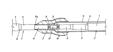
~s diagrammatically shown in Fig. 1, the junction between
two cables 1, 2 has been carried out by disposing the ends of the
cables to be joined in faced relationship, and from the ends of
the conductors 3, the respective layers having been stepwise
removed so that the conductors are bare over a given length.
The cable coverings are removed by baring the insulated
layer ~, the semiconductive layer 5, the armoring 6 and removing
the outer sheath 7 over a certain length thereof.
The bare end portions of conductors 3 are electrically
connected to each other by a junction means 8. Said electrical
junction means 8, diagrammatically shown in Fig. l, is known per
se, and it may be, for example, a weldment, a scarfing element or
the like. Therefore, the junction means 8 will not be herein
described in greater detail.
The space corresponding to the area where the insulating
layer has been removed, after the conductors have been
electrically connected to each other is filled with a sealing
compound 9 having a high dielectric constant which also is well
known in the art. The sealing compound 9 is also disposed close
3a to the transition area 9a between the outer semiconductive layer 5
and the cable insulating layer 4 in order to eliminate the step
formed therebetween.
6
r
A sleeve 10 made of cross-linked polymeric material is
arranged an the junction area to cover it. The sleeve 10 is
slidably fitted on one of the cables, before the conductors 3 are
joined, and after the electrical connection operations have been
completed by the use of the junction means 8 and by applying the
filler 9, the sleeve 10 itself is brought over the junction area
where it is released so as to form a cover around the uncovered
lengths o.f the insulating layer 4.
Before the sleeve 10 is applied over one o.f the cables as
aforesaid, the sleeve 10 is mounted around a tubular support body
I1 which keeps it in a radially expanded condition, its inner
diameter being sufficient to allow the sleeve itsel.~ and the
tubular body carrying it to freely slide on the cables.
In order to apply the sleeve 10 around the junction, the
tubular body 11, as diagrammatically shown in Fig. 1, is
progressively removed using known techniques, for example, by
axial withdrawal, so that the sleeve can elastically shrink
around the surfaces of the cable insulating layer while ejecting
the air from the areas in contact therewith and adhering to said
surfaces while exerting a certain pressure thereon in order to ,
ensure a correct distribution of the electric field in the
junction area. For medium voltage cables (Um ~ 12 RV), for
example, this pressure must be higher than a minimum value of
about 0.1 MPa.
For such purpose, the sleeve 10 is required to have an inner
diameter at rest, that is, in the absence of radially applied
stresses, less than the outer diameter of 'the cables by an amount
giving rise to an elastic deformation of the sleeve corresponding
to the desired clamping of said sleeve an the cables. In ether
words, the bore of the sleeve 10 must have an interference fit
with the diameter of the cable insulation 4 so as to be in
elastically deformed condition when it engages the insulation 4.
7
~~J~
The required degree of elastic stretch for developing a
certain pressure depends firstly, on the deformability o.~ the
material of which the sleeve is made, that is on its modulus of
elasticity E.
This modulus of elasticity for the materials commonly
adapted for use in this application is in the range of 5 to
0.5 MPa. Secondly, it depends on the radial thickness o.f the
sleeve.
Taking into account the materials commonly used and the
sizes suitable for the intended applications, a sufficient
clamping of the sleeve on the cable can be achieved by a
difference between the sleeve bore and the outer diameter of the
cable greater than or equal to 10~ when the modulus of elastic ity
is at least 0.5 MPa and the wall thickness is at least 8 mm.
A sleeve 10 adapted to the end is shown in Fig. 2 in the
rest condition, that is, in a radially non-expanded condition.
It has a central bore 12, an inner layer l0a which is a voltage
divider and is made of a material having a high dielectric
constant ~ , an intermediate layer lOb made of insulating material
and an outer layer lOc made of a semiconductive material.
The materials used for the manufacture of the sleeves are
cross-linked polymeric materials consisting of compounds having
the required electrical characteristics, but which, in addition,
must have elastic properties ensuring their clamping around the
cables as shown in Fig. 1.
Based on the sizes required for the electrical requirements,
layers l0a and lOc have a much smaller thickness than the
insulating layer lOb which, under these conditions, is,
therefore, substantially entirely responsible for the correct
clamping of the whole sleeve, the radial pressure provided by the
two other layers being neglible.
The sleeve in accordance with the invention can be used for
8
junctions for cables of several sizes, thereby reducing the
necessity of storing several series of sleeves adapted to
different cable diameters.
For the purposes of the invention, the sleeve 10 is
stretched over the tubular support 11, as shown in Fig. 3, to an
inner diamete r 1 which is big enough to be fitted on cables
having the largest diameter, the overall dimension of which is
shown in the figure in dotted lines and by reference C~.
Similarly, the sleeve must. be adapted to clamp with sufficient
pressure, as previously stated, around cables having the smallest
diameter in the group of different sizes for which said sleeve is
intended, as shown in Fig. 4, and therefore, around a cable
having an overall dimension ident~.fied by Cm in Fig. 3.
In particular, in order that a sleeve 10 can be used with a
group of cables in which the diameter of the largest diameter
cable is 60~ greater than the diameter of the smallest cable, as
in the case of cables of a 20 mm diameter and 32 mm diameter, for
example, the required expansion of the sleeve must be such as to
have an inner bore diameter of about 40 mm, taking into account
the sizes of a tubular support body 11 necessary for mounting and
which must be adapted to be fitted on the largest diameter one of
the intended cables, while providing, at the same time, a
shrinkage of the sleeve 10, at it s release, such that it reaches
a diameter of 18 mm in order to enable it to fit around the
smallest cables with a minimum elastic distension of 10~.
The sleeves can be stored under undeformed conditions and
expanded on the respective tubular support bodies in the field,
immediately before their use, but preferably, the sleeves should
be mounted on the tubular bodies at the factory under controlled
conditions and stored in an expanded state until the moment of
use, generally for a period of some months.
kIowever, the materials used for manufacturing the sleeves
9
still have a certain degree of deformation after a period of time
of stretching by the body 11. In other words, if they are
expanded, starting from a given value of inner diameter, and kept
in this state for some time, they elastically return to a
diameter larger than the original one when released from 'the body
11, and therefore, they have a certain deformation which is not
immediately recovered and which is partly or completely reduced
only after a long period, that is weeks or months, at room
temperature lower than 30°C, particularly when the deformed
condition has been maintained for a long time as in the case of
sleeves mounted on a support at the factory and stored far some
months in the expanded condition until the moment of vrse.
Therefore, in order to achieve a sufficient clamping value
of the sleeve on the cables starting from the moment the sleeve is
fitted thereon, at room temperature, without having to wait for
the final deformation recovery time before putting the cable into
service, which time would be unacceptable when common
applications are concerned, it is necessary to consider this
incomplete return to normal size after deformation as well so
that when the sleeve is released on the cables, it can
immediately provide the necessary degree of radial pressure
required fox proper clamping.
The residual deformation, or at least temporarily retained
deformation, of the material depends on the value of the imposed
deformation, the test methods, and the holding time and
temperature while the sleeve 10 is in the deformed state. Fig. 5
is a diagram illustrating, by way of example, the correlation
between the percent deformation D imposed on the material and
maintained for ~0 days at 65°C and the respective residual
deformations d, for some materials adapted to be used in making
the insulating layer lOb.
The stated time and temperature conditions substantially
2~~~J~
correspond to a two year stay at room temperature and, therefore,
simulate, in an accelerated manner, the conditions at the moment
of use of a sleeve which has been expanded at the factory and
after a period of storage, thereby constituting an appropriate
reference value for evaluating the elastic behavior of the
material.
The line 13 represents the desired correlation between the
imposed deformation D and residual deformation d so that a
material following an imposed expansion from an initial diameter
until the desired maximum diameter of 40 mm, may elastically come
back to the diameter of 18 mm corresponding to a diameter IO$
less than the insulation 4 of a cable having a diameter of 20 mm.
Fig. 5 indicates that an elastomeric material which can be
expanded and comprised within the area located to the right of
line 13 can be used to make the insulating layer in the sleeve.
In fact, using a material, for example, of the type showing a
correlation corresponding to curve 14 between imposed expansion D
and residual deformation d, it is possible to find an imposed
expansion value Dml of approximately 170 at which an
instantaneous residual deformation of about 23$ is obtained.
Therefore, starting from a diameter ~0 at rest of 14.5 mm, a
diameter of 18 mm at the release can be reached as desired, which
ensures the desired release diameter of the bore 12 which is l0a
less than the insulation diameter of a cable having the smallest
diameter can be obtained.
Even if a material with lower elastic characteristics is
used, that is, a material allowing a greater temporary residual
deformation as shown by curve 15 in Fig. 5, it is possible to
find an imposed expansion value Dm2 of 320 at which a .residual
deformation of 90$ is obtained, so that a diameter ~0 at rest of
9.5 mm can be selected, which diameter allows a diameter value o:~
18 mm at the release to be reached even taking into account a
11
residual deformation of 90~.
Higher values of the imposed expansion, that is lower values
of ~0 in the sleeve are applicable as well, provided that the
diameter under expansion conditions is the same and that for the
various compounds points along the curves 14, 15 located to the
right of the intersection with line 13 are selected. These
values will bring to correspondingly higher diameter difference
values of the sleeve with the cable at the release.
The above stated elastic characteristics must be associated
with an ultimate deformation value of the selected compound
capable of ensuring that the imposed expansion leading to the
desired clamping can be reached without tearing of the sleeve and
at all events, to a critical stress value.
Tn addition, the residual deformation does not take into
account the initial ultimate expansion value of the compound
forming the insulating layer in the sleeve because when the
sleeve has been left at the expanded state for a long period of
time, on the order of some months, critical conditions can be
reached also in the presence of expansion values lower than the
above initial ultimate expansion. Such ultimate expansion
values, where the expansion is maintained over the course of
time, are shown in Fig. 5 by points DR.
Therefore, for the selected compound, it is necessary to set
the ultimate expansion value taking into account the fact that
the expansion must be maintained for a predetermined period of
time, six months .for example, as well as a permissible safety
value DRam related thereto, and to be sure that the desired
expansion value for the sleeve is included within the minimum
expansion Dm and the maximum permitted expansion Dga:m°
As shown in Fig. 5, a compound behaving in accordance with
the curve 16 and exhibiting a high residual deformation could be
used as well by selecting a starting diameter involving an
12
expansion at least equal to Dm3 so as to go to the right of line
13, but if the permissible ultimate expansion value DR, as above
stated, is lower than value Dm3, it is impossible to make a
practical sleeve with such compound.
The preferred expansion range of the sleeve support
according to the invention provides imposed expansions in the
range of 120 to 320 and preferably between 150 and 250.
As the sleeve is a solid tubular body of relatively large
thickness, the percent expansion is not constant over the whole
sleeve but decreases from the axis towards the periphery, the
most critical conditions for the material used, that is to say
the greatest percent expansions, occurring in the areas which are
the closest to the central bore, the conditions becoming less
severe when moving towards the outside.
Therefore, the voltage dividing layer l0a which is the most
stressed by the imposed radial expansion, is required to be made
of a material having, at the intended storage conditions and for
the intended storage time in the expanded state, mechanical
properties adapted to make it withstand the imposed expansion
values. On the other hand, this material, due to the reduced
thickness of the layer, usually lower by 10~ than the overall
sleeve thickness, does not greatly affect the clamping of the
sleeve as a whole.
Under operating conditions, once the sleeves have been
mounted on the cables, they are in a state of less severe
expansion. On the other hand, due to the fact that the cable in
its operating conditions must work at much higher temperatures
than the room temperature, usually at 90°C, and sometimes higher
temperatures for a reduced period of time, it also is clear that
the sleeves applied to the cable junctions must be able to
withstand such temperatures and still operate safely.
This fact does not create any difficulty when the sleeves
13
are applied to cables of the smallest size, because when they are
mounted on the cables, their innermost layers are subjected to a
reduced expansion. On the contrary, when the sleeves are mounted
on cables of the largest size, they are in a state of high radial
expansion because their shrinkage takes place on a diameter
greater by 60~ than the minimum one.
For example, a sleeve having an inner diameter at rest o:E
9.5 mm and applied to cables of a 32 mm diameter is expanded by
23~~. In order to allow the sleeve to withstand such a condition
with an appropriate safety margin, the insulating layer lOb of
the sleeve as well as the innermost layer l0a must have an
ultimate elongation value, that is, a permissible elongation
before fracture, at least as high as 300 at the operating
temperature of the cable.
By way of example, a compound of a cross-linked polymeric
material having the stated features and adapted to be used for
making the insulating layer lOb, has the following composition
(expressed in parts by weight):
- ethylene-propylene copolymer, for example,
the one sold in the market under the name
DUTRAL CO-054 by DUTRAL S.p.A. 100
- polyisobutylene, for example, the one
sold in the market under the name
OPPANOL B 200 by BASF 22
- calcined kaolin 80
- trimthoxyethoxy vinylsilane 1.5
- paraffin wax 2.5
- zinc oxide 5
- lead tetroxide (Pb304) 7
- liguid cis-1,2-polybutadiene 6
- poly-1,2-dihydro-2,2,4-trimthyl quinoline 1.5
- sulfur 0.47
14
- l,l-bis-tert-butylperoxy-3,3,5-trimthyl cyclohexane 4.2
The physical characteristics of the sleeve layer lOb made
with said compound, after cross-linking, are as follows:
- tensile breaking strength 7 MPa
- maximum permissible expansion at room temperature,
held for a period of six months X400$
- maximum permissible expansion at 100°C,
held for a period of six months >300$
- modulus of elasticity E 1.8 MPa
- residual deformation at an imposed radial
expansion of 320, held for 40 days at 65°C,
determined according to UNI specification 7321-74 90~
- dielectric constant E determined according to
ASTM specifications D150 3
- volume resistivity determined according to
ASTM specifications'D257 10150hm x cm
An example of a compound of a cross-linked polymeric material
having the stated features as regards deformability and strength
and adapted to be used for making the inner layer 10a, has the
following composition (expressed in parts by weight)e
- ethylene-propylene copolymer, for example
the one sold in the market under the name
DUTRAL CO-054 by DUTRAL S.p.A. 100
- zinc oxide 5
- carbon black, for example, the one sold
in the market under the name
HUBER N 990 sold by DEGUSSA S.p.A. 140
- paraffin plasticizer 40
- poly-1,2-dihydro-2,2,4-trimethyl quinoline 1.5
- stearic acid 1
- triallyl cyanidate 1
- cumene hydroperoxide 2
2~2~~~~
The physical characteristics of the sleeve layer l0a made
with said compound, after cross-linking, are as follows:
- tensile breaking strength 7 MPa
- maximum permissible expansion at room temperature,
held for a period of six months '400
- maximum permissible expansion at 100°C, held for
a period of six months X300$
- modulus of elasticity E 1.5 MPa
- residual deformation at an imposed
radial expansion of 300, held for 40 days at
65°C, determined according to UNI speci:Eications
7321-74 g0~
- dielectric constant ~ determined according to
ASTM specifications D150 15
- volume resistivity determined according to
ASTM specifications D257 1010 Ohm x cm
If, for reasons different from the mechanical ones taken
into account, different relative thicknesses between the various
layers forming the sleeve are required, the conditions of limited
residual deformation as above stated could be applied not only to
the insulating layer but also to one or more of the other layers,
based on their state of stress and on their contribution to the
elastic behavior of the assembly.
Although preferred embodiments of the present invention have
been described and illustrated, it will be apparent to those
skilled in the art that various modifications may be made without
departing .from the principles of the invention.
16