Sélection de la langue

Search

Sommaire du brevet 2022859 

Énoncé de désistement de responsabilité concernant l'information provenant de tiers

Une partie des informations de ce site Web a été fournie par des sources externes. Le gouvernement du Canada n'assume aucune responsabilité concernant la précision, l'actualité ou la fiabilité des informations fournies par les sources externes. Les utilisateurs qui désirent employer cette information devraient consulter directement la source des informations. Le contenu fourni par les sources externes n'est pas assujetti aux exigences sur les langues officielles, la protection des renseignements personnels et l'accessibilité.

Disponibilité de l'Abrégé et des Revendications

L'apparition de différences dans le texte et l'image des Revendications et de l'Abrégé dépend du moment auquel le document est publié. Les textes des Revendications et de l'Abrégé sont affichés :

  • lorsque la demande peut être examinée par le public;
  • lorsque le brevet est émis (délivrance).
(12) Brevet: (11) CA 2022859
(54) Titre français: CALE ET SUPPORT POUR CARTE DE CIRCUITS
(54) Titre anglais: CIRCUIT BOARD SPACING AND SUPPORT APPARATUS
Statut: Périmé et au-delà du délai pour l’annulation
Données bibliographiques
(51) Classification internationale des brevets (CIB):
  • H05K 07/12 (2006.01)
  • F16B 05/06 (2006.01)
  • H05K 07/14 (2006.01)
(72) Inventeurs :
  • NOVAK, CARL V. (Etats-Unis d'Amérique)
(73) Titulaires :
  • MOTOROLA, INC.
(71) Demandeurs :
  • MOTOROLA, INC. (Etats-Unis d'Amérique)
(74) Agent: GOWLING WLG (CANADA) LLP
(74) Co-agent:
(45) Délivré: 1993-06-22
(22) Date de dépôt: 1990-08-08
(41) Mise à la disponibilité du public: 1991-05-22
Requête d'examen: 1990-08-08
Licence disponible: S.O.
Cédé au domaine public: S.O.
(25) Langue des documents déposés: Anglais

Traité de coopération en matière de brevets (PCT): Non

(30) Données de priorité de la demande:
Numéro de la demande Pays / territoire Date
439,951 (Etats-Unis d'Amérique) 1989-11-21

Abrégés

Abrégé anglais


CIRCUIT BOARD SPACING AND SUPPORT APPARATUS
Abstract of the Disclosure
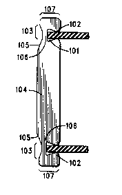
A single piece of material having notches (101), on the
same side, on each end of the apparatus. An indentation (103)
opposite each notch (101) creates a narrow, flexible region
(106) on each end of the apparatus. A printed circuit board
inserted in one of the notches (101) will cause the lower portion
(107) below the notch (101) to flex, thereby allowing the board
entry into the narrow notch (101) opening. Once the board has
been inserted, the resilient material of the apparatus will
cause the flexed lower portion (107) to attempt to return to its
original shape. This will force the lower portion (107) of the
notch (101) up against the board thereby holding the board in
place against the upper portion of the notch (101). This simple
design allows the apparatus to be manufactured relatively
inexpensively.

Revendications

Note : Les revendications sont présentées dans la langue officielle dans laquelle elles ont été soumises.


-6-
I claim:
1. A circuit board spacing ant support apparatus,
comprising:
a) a flat, elongated center section having a first end and
a second end and a first side and a second side parallel to the
first side;
b) the first side of the flat, elongated center section
having a first notch a first predetermined distance from the
first end and the first side of the flat, elongated center section
having a second notch a second predetermined distance from
the second end, the first notch having a first predetermined
depth and width and the second notche having a second
predetermined depth and width;
c) the second side of the flat, elongated center section
having a first depressed region coupled to the first end by a
first segment of a first predetermined length wherein the first
depressed region is located substantially opposite the first
notch and the first segment is parallel to and offset from the
second side; and
d) the second side of the flat, elongated center section
having a second depressed region coupled to the second end by
a second segment of a second predetermined length wherein
the second depressed region is located substantially opposite
the second notch and the second segment is parallel to and
offset from the second side.

-7-
2. The apparatus of claim 1 wherein the first and second
predetermined distances are .090 inches.
3. The apparatus of claim 1 wherein the the first and second
predetermined widths are .057 inches and the first and second
predetermined depths are .075 inches.
4. The apparatus of claim 1 wherein the first and second
depressed regions are depressed .03 inches from the second
side.
5. The apparatus of claim 1 wherein the first and second
segments are offset from the second side by .015 inches in the
direction of the first side.
6. The apparatus of claim 1 wherein the first notch has a first
wall facing a second wall, the first and second walls coupled
to a common third wall wherein the third wall is longer than
an opening of the first notch.
7. The apparatus of claim 1 wherein the second notch has a
first wall facing a second wall, the first and second walls
coupled to a common third wall wherein the third wall is
longer than an opening of the second notch.

Description

Note : Les descriptions sont présentées dans la langue officielle dans laquelle elles ont été soumises.

- 1 - OE00164R
CIRCUIT BOARD SPACING AND SUPPORT APPARATUS
Fi~ld of tl~ Inv~ntion
This invention relates generally to the electronic
assembly field and particularly to the circuit board ~pacer and
support field.
15 Backezound of th~ In~iQ~
When more than one printed circuit board is installed
in a device, they may be mounted one above the other to reduce
the amount of space required. Spacing supporters are
2 0 typically used to separate the boards for better cooling air flow
and to reduce the risk of contact of circuits on the separate
boards.
Spacing ~upporters are manufactured in various
shapes and sizes depending an the application. The distance
2 5 required between boards typically determines the length of the
spacing supporter. The board's density typically determines
the type of spacing supporter required.
Spacing supporters can be of two types: one type i8
inserted in a hole in the board and another is attached to the
3 0 edge of the board. A spacing supporter that i8 inserted in a
hole in the board cannot be used with a dense board since the
hole takes up valuable room. In this situation, a spacing
supporter that attaches to the side of the board is typically
used.
3 5 A problem with edge of board supporters is that the
opening in the support that retains the circuit board is
:- . . : - - ~ ;,
~"

- 2 - CE00164R
typically sized 90 a~ to accept a board in it~ worst case thickest
condit;on. This mean~ that acceptable boards that are even
slightly thinner can rattle and move about. This is
unacceptable with respect to vibration, audible noise, and
movement induced circuit noise.
Both type~ of spacing supporters have the common
problem of being comple~ly shaped. The complex designs
require expensive tooling to manufacture the spacing
supporters. This in tu~ leads to more expensive spacing
1 0 supporters. There is a resulting need for a less costly printed
circuit board spacing supporter that can be used with dense
boards and that retains the circuit board rigidly without
requiring additional elements.
1 S ~mmarv of ~h~
The present invention separates and rigidly supports
printed circuit boards. This apparatus is manufactured as a
single, rectangularly shaped strip of material Each end of the
2 0 strip contains a notch on the same side. On the opposite side
of and immediately behind the notches, are shallow
indentations. The width of the apparatus from the end of each
indentation to each end of the apparatus i8 less than the w~dth
of the mit-section af the apparatus.
2 5 The dimensions of the spacing supporter apparatus are
dependent on the application. A longer apparatus and a
greater distance between notches is required for an
application requiring a greater distance between circuit
boards. The dimensions of the notches are dependent on the
3 0 thickness of the circuit boards.
The notches are positioned on the edges of the circuit
boards to be separated, the upper notch of the apparatus is
attached to the upper board and the lower notch to the lower
board. The smaller width of the apparatus at the point of the
3 5 notch and indentation allows that part to flex around the
. . . .
:
.~ ' ; ' .
. '
.

- 3 - CE00164R
board~ holding it tightly as compared to current non-flexing
notche~.
Brief De~d~Q~ the I~ vin~
,~, 5
y FIG. 1 show the present invention in a typical application;
FIG. 2 shows a close up of one end of the pre~ent invention;
, and
~ FIG. 3 shows a close up of one end of the present invention
;~ l 0 indicating various angles.
FIG. 4 shows the present invention used with a worst case
thickness circuit board.
Be~ Mode fo~ C~e Out the Invent~
:; 1 5
The present invention separates and rigidly supports
printed circuit boards installed within an electronic device.
The apparatus, the preferred embodiment illustrated in Fig.
1, can function using minimal board space. In addition, due
2 0 to the simplicity of design, it can be manufactured relatively
inexpensively.
The apparatus i8 manufactured from a single piece of
material, the preferret embotiment being plastic. The
material used must be resilient, allowing the apparatus to flex
2 5 without breaking and to return to its original shape after use.
The apparatus includes notches (101) on the same side
at each end. The center of each notch (101) is located
approsimately .090 inches from the end. The width of the
notch (101) opening, .057 i .002 inches in the preferred
3 0 embodiment, accommodates a stantard width printed circuit
board. The sides of the notches (101) that face each other are
angled outward by approximately 15 a~ illustrated in Fig. 3.
This creates an opening of each of the notches (101) that is
narrower than the rest of the notch (101).
3 5 At each end on the opposite side of the apparatus,
im nediately behind each notch (101), is an indentation (103).
. .,. ~
- . .
, .
.. . . .
. . .

- 4 - CE00164R
These shallow indentations (103) are .030 inches deep as
measured from the mid-section (104) of the apparatus. The
initial ~lope (105) ofthe indentation (103) is approximately 30
from the mid-section (104) as illustrated in Fig. 3. These
S intentations (103) may be flat as shown in Fig. 1 or form a
radiu~ a~ shown in Fig. 3. The indentation (103), in
conjunction with the notch (101), creates a narrow, flexible
section (106) at each end of the apparatus.
The end section (107) of the apparatus after the
l O indentation is a narrower width than the mid-section (104).
The width of the mid-~ection (104) i~ approximately .130 inches
while the end sections (107) are approximately .115 inches.
The circuit board spacing and support apparatus
operates, as illustrated in Fig. 1 and Fig. 2, by inserting a
15 board in each notch (101). For correct operation, the opening
of the notch (101) should be narrower than the thicknes~ of the
circuit board. The narrow, flexible region (106) created by the
combination of a notch (101) and an indentation (103) fle~ces,
allowing the thicker board to be inserted. Once the board is
2 0 inserted, the flexible part, attempting to return to its original
shape, will force the upper part of the notch (102) to put
pressure on the board. This pressure will hold the board in
place against the lower part of the notch. Due to the small
area that is in contact ~qith the board, minimal board space is
2 S required to hold the board solidly.
Fig. 4 illustrates the present invention used ~nth a
circuit board having a worst case thickness. The narrower
end of the apparatus can fle~c back without protruding past the
oubide surface of the apparatus. This allows the apparatus to
3 0 be used with thicker boards without requiring additional
space.
The dimensions and material of this apparatus will
vary depending on the application. The length of the
apparatus and the distance between the notches (101) will vary
3 5 depending on the distance required between the boards. The
thickness of the apparatus will vary depending on the
,

- 5 - CE00164R
~ 3 ~-9
strength required. The apparatus's composition msy be a
; high temperature material when the environment has a high
ambient temperature.
l~e printed circuit board spacing and support
S apparatus di~closed above is relatively ine~pensive to
manufacture due to its ~imple de~ign. An additional benefit is
that very little board space i8 required since holes in the board
are not needed and the apparatus rigidly grips the board with
a small surface area.
10Those skilled in the art vill recognize that various
modifications and changes could be made to the invention
~vithout departing from the spirit and scope thereof. It should
therefore be understood that the claims are not to be
considered as being limited to the precise embodiments set
l S forth in the absence of specific limitations directed to such
embodiments.
.. ~' - . ': .
, .

Dessin représentatif
Une figure unique qui représente un dessin illustrant l'invention.
États administratifs

2024-08-01 : Dans le cadre de la transition vers les Brevets de nouvelle génération (BNG), la base de données sur les brevets canadiens (BDBC) contient désormais un Historique d'événement plus détaillé, qui reproduit le Journal des événements de notre nouvelle solution interne.

Veuillez noter que les événements débutant par « Inactive : » se réfèrent à des événements qui ne sont plus utilisés dans notre nouvelle solution interne.

Pour une meilleure compréhension de l'état de la demande ou brevet qui figure sur cette page, la rubrique Mise en garde , et les descriptions de Brevet , Historique d'événement , Taxes périodiques et Historique des paiements devraient être consultées.

Historique d'événement

Description Date
Inactive : CIB de MCD 2006-03-11
Le délai pour l'annulation est expiré 1998-08-10
Lettre envoyée 1997-08-08
Accordé par délivrance 1993-06-22
Demande publiée (accessible au public) 1991-05-22
Toutes les exigences pour l'examen - jugée conforme 1990-08-08
Exigences pour une requête d'examen - jugée conforme 1990-08-08

Historique d'abandonnement

Il n'y a pas d'historique d'abandonnement

Titulaires au dossier

Les titulaires actuels et antérieures au dossier sont affichés en ordre alphabétique.

Titulaires actuels au dossier
MOTOROLA, INC.
Titulaires antérieures au dossier
CARL V. NOVAK
Les propriétaires antérieurs qui ne figurent pas dans la liste des « Propriétaires au dossier » apparaîtront dans d'autres documents au dossier.
Documents

Pour visionner les fichiers sélectionnés, entrer le code reCAPTCHA :


Pour visualiser une image, cliquer sur un lien dans la colonne description du document. Pour télécharger l'image (les images), cliquer l'une ou plusieurs cases à cocher dans la première colonne et ensuite cliquer sur le bouton "Télécharger sélection en format PDF (archive Zip)" ou le bouton "Télécharger sélection (en un fichier PDF fusionné)".

Liste des documents de brevet publiés et non publiés sur la BDBC .

Si vous avez des difficultés à accéder au contenu, veuillez communiquer avec le Centre de services à la clientèle au 1-866-997-1936, ou envoyer un courriel au Centre de service à la clientèle de l'OPIC.


Description du
Document 
Date
(aaaa-mm-jj) 
Nombre de pages   Taille de l'image (Ko) 
Abrégé 1994-07-08 1 17
Revendications 1994-07-08 2 53
Dessins 1994-07-08 1 18
Description 1994-07-08 5 173
Dessin représentatif 1999-07-18 1 5
Avis concernant la taxe de maintien 1997-09-30 1 179
Taxes 1994-06-16 1 85
Taxes 1996-07-14 1 80
Taxes 1995-07-16 1 69
Taxes 1992-06-28 1 107
Taxes 1993-06-23 1 46
Courtoisie - Lettre du bureau 1991-02-07 1 22
Correspondance reliée au PCT 1993-04-14 1 27