Sélection de la langue

Search

Sommaire du brevet 2023220 

Énoncé de désistement de responsabilité concernant l'information provenant de tiers

Une partie des informations de ce site Web a été fournie par des sources externes. Le gouvernement du Canada n'assume aucune responsabilité concernant la précision, l'actualité ou la fiabilité des informations fournies par les sources externes. Les utilisateurs qui désirent employer cette information devraient consulter directement la source des informations. Le contenu fourni par les sources externes n'est pas assujetti aux exigences sur les langues officielles, la protection des renseignements personnels et l'accessibilité.

Disponibilité de l'Abrégé et des Revendications

L'apparition de différences dans le texte et l'image des Revendications et de l'Abrégé dépend du moment auquel le document est publié. Les textes des Revendications et de l'Abrégé sont affichés :

  • lorsque la demande peut être examinée par le public;
  • lorsque le brevet est émis (délivrance).
(12) Brevet: (11) CA 2023220
(54) Titre français: ELEMENT CORNIER FLEXIBLE POUR BATI INTERCALEUR DESTINE A UN PANNEAU DE VITRAGE ISOLANT
(54) Titre anglais: FLEXIBLE CORNERPIECE FOR SPACER FRAME FOR INSULATED GLASS PANEL
Statut: Réputé périmé
Données bibliographiques
(52) Classification canadienne des brevets (CCB):
  • 108/32.7
(51) Classification internationale des brevets (CIB):
  • E06B 3/24 (2006.01)
  • E06B 3/667 (2006.01)
(72) Inventeurs :
  • PETERSON, LARRY WALLACE (Etats-Unis d'Amérique)
(73) Titulaires :
  • ALUMET MFG., INC. (Etats-Unis d'Amérique)
(71) Demandeurs :
(74) Agent: SMART & BIGGAR
(74) Co-agent:
(45) Délivré: 1997-09-09
(22) Date de dépôt: 1990-08-14
(41) Mise à la disponibilité du public: 1991-02-17
Requête d'examen: 1994-05-12
Licence disponible: S.O.
(25) Langue des documents déposés: Anglais

Traité de coopération en matière de brevets (PCT): Non

(30) Données de priorité de la demande:
Numéro de la demande Pays / territoire Date
394,736 Etats-Unis d'Amérique 1989-08-16

Abrégés

Abrégé français

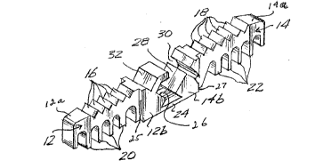
tructure d'écartement servant à séparer les carreaux de vitre d'un panneau de verre isolant, muni d'un écoinçon comportant un premier et un deuxième bras reliés au moyen d'une charnière flexible pour permettre aux bras en question de se déplacer l'un par rapport à l'autre selon un mouvement angulaire. Ce premier et ce deuxième bras comprennent tous les deux une première partie dont la section transversale représente une surface sensiblement égale à celle de la section transversale d'un liteau d'écartement dans lequel ils sont insérés, et une deuxième partie faisant saillie par rapport à ce liteau d'écartement, qui se situe dans une section transversale plus grande que la première partie en question pour former un renflement adjacent et contigu à l'extrémité du liteau d'écartement. Ce renflement est sensiblement continu sur tout son périmètre afin d'éliminer considérablement les voies d'accès à l'humidité provenant de l'extérieur de ce liteau d'écartement. Le coin plié forme un bloc solide qui empêche l'humidité de pénétrer dans le liteau d'écartement. L'écoinçon comporte également une avancée angulaire qui va d'une première extrémité du premier bras à une fente apparaissant au niveau de la première extrémité du deuxième bras, l'avancée et la fente contribuant conjointement à constituer un joint à ajustement serré qui maintient ensemble de manière non permanente le premier et le deuxième bras selon l'angle voulu. Une première surface de chacun de ces premier et deuxième bras présente une série de striations en dent de scie qui entrent en contact avec la surface interne du liteau d'écartement pour favoriser le maintien du bras dans le liteau d'écartement.


Abrégé anglais


In a spacer frame for use in separating panes of glass of an insulated glass
panel, a cornerpiece has first and second arms joined by a flexible hinge to permit
angular movement of said arms with respect to one another. The first and second
arms each have a first portion that has a cross-sectional area substantially equal
to the cross-sectional area of a spacer bar into which they are inserted, and a
second portion that protrudes from the spacer bar that is of a cross section larger
than said first portion to form a shoulder that is adjacent and abutting the end of
the spacer bar. The shoulder is substantially continuous around its perimeter tosubstantially eliminate moisture paths from outside said spacer bar to the interior
of the spacer bar. The folded corner presents an essentially solid mass that
prevents moisture from entering the spacer bar. The cornerpiece also includes anangled projection that extends from a first end of the first arm and a slot formed
in the first end of the second arm, the projection and slot cooperating with oneanother to form an interference fit that releasably holds the first and second arms
in a desired angular relationship. A first surface of each of said first and second
arms has a series of sawtooth-like serrations formed thereon that interferes with
an interior surface of the spacer bar to aid in maintaining the arm in the spacer
bar.

Revendications

Note : Les revendications sont présentées dans la langue officielle dans laquelle elles ont été soumises.


- 6 -

The embodiments of the invention in which an exclusive property or privilege
is claimed are defined as follows:

1. A cornerpiece for joining adjacent tubular spacer bars in a spacer
frame for an insulated glass panel, said cornerpiece comprising:
a first arm of cross section substantially equal to the cross section of said
spacer bar;
a second arm of cross section substantially equal to the cross section of said
spacer bar;
a flexible joint means connecting said first and second arms;
a series of sawtooth projections protruding from a first surface of each of
said first and second arms, said sawtooth projections adapted to interact with an
interior serrated wall of said spacer tubes to interfere with removal of said arms
from said spacer tubes; and
an angled projection protruding from a first end of said first arm adjacent
the flexible joint means, said angled projection constructed and arranged to
cooperate with an angled slot formed in a first end of said second arm adjacent said
flexible joint means to provide interference between a corner of said angled
projection and a corner formed in said angled slot.

2. The cornerpiece of Claim 1, wherein said first and second arms, said
flexible joint means, and said angled protrusion are contiguously formed of a
single piece of plastic material.

3. The cornerpiece of Claim 2, wherein each of said first and second
arms have a first solid portion and a second tab portion, the total cross section of
said solid portion and said tab portion being substantially equal to the cross section
of said spacer bar.

4. A spacer frame for use in separating the panes of glass of an insulated
glass panel comprising a plurality of hollow tubular spacer bars, adjacent ones of
said spacer bars being joined by a cornerpiece having first and second arms insertable
into adjacent ones of said spacer bars to form corners of said frame, said
first and second arms being connected by flexible joint means to allow the positioning
of said arms at a desired angle for said corner; and
each of said arms having a first portion insertable into said spacer bar and a
second portion that extends from said spacer bar, said second portion being


- 7 -
substantially solid around the entire periphery of engagement with said spacer bar to
substantially eliminate any moisture path from the interior of said spacer bar to
the exterior of said spacer bar.

5. The spacer frame of Claim 4, wherein said first and second arms and
said flexible joint means of said cornerpiece are constructed of a single piece of
plastic material.

6. The spacer frame of Claim 5, wherein said plastic material is nylon.

7. The spacer frame of Claim 5, wherein said first and second arms
include sawtooth projections extending from a first surface of each of said first
and second arms, said sawtooth projections engaging an inner wall of said spacerbar to create an interference fit that resists removal of said arm from said spacer
bar.

8. The spacer frame of Claim 7, wherein said first arm includes an
angular projection having a first portion extending from a first end of said first
arm and a second portion angled with respect to said first portion to form an
inside corner, said first projection being constructed and arranged to cooperatewith a slot formed in a first end of said second arm, said slot having a first portion
that extends from the surface of said first end of said arm and a second portioncontiguous with said first portion and angled with respect thereto to form an
inside corner of said slot, said inside corner of said projection interfering with said
inside corner of said slot to provide sufficient force to releasably hold said first
and second arms at a predetermined angle with respect to one another.

9. The spacer frame of Claim 4, wherein each of said first and second
arms includes a first portion having a cross-sectional area substantially equal to
the cross-sectional area of said spacer bar and a second portion having a
cross-sectional area larger than the cross-sectional area of said first portion, said first
and second portions meeting to form a shoulder that abuts a first edge of of a first
end of said spacer bar when said first portion is inserted into said spacer bar, said
shoulder being substantially continuous around its perimeter to eliminate moisture
paths from within said spacer bar to the exterior of said spacer bar.

Description

Note : Les descriptions sont présentées dans la langue officielle dans laquelle elles ont été soumises.


- 1- 2~2~


p~ Rr.~. CORNP.RPlECg FOR SPACER F3'cA~l~
FOR INSULATl~D GLASS PANEL
Background of the Invention
The present invention reIates to frames for insulated glass panels and, in
5 particular, to a cornerpiece for connecting the discrete sections of the frame.
It is well known in the art to provide a window halr;ng more than one pane of
glass, the panes being separated by an air space. Such windows are known as
insulating windows or insulated glass panels by virtue of the fact that the air
trapped within the space between the panes of glass serves as an insulator to
10 reduce heat flow through the glass. Typically the panes of glass are separated by
a frame comprised of sections of tubing joined together at adjacent ends to form a
continuous frarne. The frame lies between the panes of glass and extends around
the perimeter of the window panes The tubes, also known as spacer bars, are
commonly made o~ aluminum or steel. In order to prevent the window panes from
15 foggin~, it is necessary to keep the air that is trapped between the window panes
as dry as possible. A desiccant, for example, silica gel, is oftentimes placed in the
spacer tubes to absorb moisture from the air trapped within the space between the
window panes. In order to prevent the desiccant from settling to the bottom oP
the tubular spacer frame when the window is in an upright position, it is necessary
20 to block the ends of the sections of spacer bar to keep the desiccant within the
separate sections of the spacer. It is also necessary to block the ends of the
spacers to prevent the desiccant from entering the space between the window
panes, causing an unsightly appearance.
Earlier cornerpieces were constructed Oe aluminum or zinc. However, ;n
25 recent years, to take advantage of lower costs of materials and fabrication,
cornerpieces of plastic or nylon have become more common. One such corner-
piece is shown in United States Patent No. 4,530,I95 to Leopold issued July 23,
1985. Leopold shows a flexible cornerpiece that has a latching means so that

- 2~ 32~

when the corner is formed to its ~inal configuration it is securely latched intoposition and cannot be unbent without exertion of some substantial force on the
corner. It has been found that such positive latching is unnecessary and it is
sufficient if the cornerpiece can be temporarily maintained in an angled position
5 during in;tial construction of the frame. Once the frame is sealed into the final
position between the glass panes, the sealant maintains the frame in its correctorientation and configuration without the need for latching of the cornerpiece. It
is also desirable to eliminate any moisture path from the end of spacer bar that is
provided by seams or voids in the cornerpiece.
Summary of the Invention
The present invention provides a flexible cornerpiece for use in the con~truc-
tion of a spacer frame for insulated glass panels that includes a first and second
arm adapted for insertion into the ends of adiacent spacer frames to join the
spacer frames together. The two arms are connected by a flexible joint area
15 bendable to place the spacer bars into the correct desired angular relationship
depending on the final shape of the frame. The first arm includes an angled slot,
and the second arm includes a cooperatively angled finger formed for insertion
into the slot. The angularity of the slot and finger provides sufficient resistance
to releasably maintain the arms at a predetermined angle temporarily but allows
20 enough ïreedom of movement to easily unbend the arms. A first surface of eachof the eirst and second arms has a series of serrations or sawtooth-like projections
formed thereon that interact with the seam of the spacer bar ~o provide inter-
ference to removal OI the arm from the spacer bar once insertion has been made.
At least a first portion of each of the first and second arms are of a cross section
25 substantially equal to the cross section of the interior of the spacer bar to block
the cross section of the spacer bar, thereby preventing the escape Oe desiccant
within the spacer bar. A second portion of each of the first and second arms is of
a larger cross section than the first portion and forms a shoulder at the transition
of the first to the second portion. The shoulder acts as a stop and abuts the end of
30 the spacer bar when the arms are inserted into the bar. The first and second arms
are constructed so that there are substantially no voids from the shoulder to the
apex of the corner when in the folded position. The essentially solid configuration
of the folded corner substantially eIiminates the moisture paths into the spacer bar.
Brief Description of the Drawings
The above-stated features and advantages of the invention will be better
understood by one of ordinary skill in the art, upon reading the enslling specifica-
tion taken in conjunction with the appended drawings, wherein:

3 ~32~

FIGURE 1 is an isometric view of a fle~ible cornerpiece made in accordance
with the principle~ of the present invention;
FIGURE 2 is a side elevational view in cross section of the cornerpiece of
FIGURE 1 engaging adjacent spacer bars; and
F~GURE 3 is a side elevational view in cross section of the cornerpie~e and
spacer bar assembly of FIGURE 2 ~orrslec~ at right angles.
Detailed Description of the Preferred Embodiment
~ preferred embodiment Oe a tlexible cornerpiece made in accordance with
the present invention is shown in FI~URE 1. The cornerpiece is shown in its
10 unflexed state and includes a first arm 12 that extends in a first direction and a
second arm 14 that extends in the opposite direction. The arms 12 and 14 each
have a substantially rectangular cross section and a Pirst surface of each of the
arms is formed with a series of serrations 16 and 18, respectively, which give the
surfaces of the arms a sawtooth appearance. A series of tabs 20 protrudes or-
15 thogonally from the second surface of the first arm opposite the serrations 18 and
a similar set of tabs 22 extends orthogonally Prom the second surface of the
second arm 14 in the direction opposite the serrations 1~. ~ first end 12a and 14a
of each arm is tapered to provide a lead-in that eases the insertion of the arm into
its respective spacer bar, as discussed below. The first and second arms are
20 connected by a hinge piece 24 that is contiguous with a second end 12b and a
second end 14b of the first and second arms, respectively. Each of the second
ends 12b and 14b of the first and second arms has a joint face 26 and 28t respec-
tively, formed thereon, which is angled obliquely to the respective first surfaces
of the first and second arms. The angle of the joint faces 26 and 28 is such that
25 when the cornerpiece is flexed into its desired angularity, for example~ as shown
in FIGURE 3, the joint faces abut one another holding the corner at the desired
minimum angle.
An angled slot 30 is formed in the joint face 28 of the second arm 14 and a
finger 32 extends from the joint face 26 of the first arm. The finger 32 has first
30 and second portions angled with respect to one another to form a corner 34. The
finger 32 is cooperatively formed with the slot 30, which has a corner 36 formedby angled adjacent slot portions so that when the cornerpiece is flexed into itsdesired angularity, as shown in FIGURE 3, the finger 32 engages the slot 30. Thecorner 36 of slot 30 provides an interference fit at the corner 34 of the finger 32
35 to hold the finger loosely in place when the finger is inserted into the slot.
FIGURE 2 shows the cornerpiece of FIGURE 1 with the respective first and
second arms 12 and 14 inserted into spacer bars 40 and ~2, respectively. Spacer

322~
bars are typically aluminum or steel tubes having an interlocking seam on their
upper surface that is engaged by the first surfaee of the first arm 12. The serra-
tions 16 form an interference fit with the interlocking seam of the spacer bar 40
to assist in holding the cornerpiece into the spacer bar. Some type of desiccant 44
is placed within the spacer bar and the cornerpiece arms are sized cooperativelywith the size of the spacer bar to eill the spacer bar and block the exit of desic-
cant 42 from the end Oe the spacer bar. While the blocking can be accomplished
by a solid arm, the tabs 2û pereorm the eunction adequately and utilize less mate-
rial than a solid corner. The second arm 14 of the cornerpiece fits into the spacer
bar 42 in the same manner and the tabs 22 block the ïlow of desiccant 44 from the
second spacer bar 42. A second portion of the arm 12 adjacent the hinge 24 has alarger cross section than the remaining portion of the arm. A shoulder 25 is
formed at the transition from the second portion of the arm to the remaining
portion of the arm.
The shoulder 25 abuts the end of the spacer bar 40 when the arm 12 is in-
serted into the bar and the shoulder 25 acts as a stop to prevent the arm 12 from
being inserted too far into the bar. A similar shoulder 27 is formed on th0 second
arm 14 and abuts the end of the spacer bar ~L2 and also acts as a stop to prevent
the arm t4 from being inserted too far into the spacer bar 42.
FIGURE 3 shows the cornerpiece in its final desired angularity as would be
found in a finished frame Ior an insulated glass panel. It can be seen that the
finger 32 is engaged in the slot 30 holding the cornerpiece loosely in its configura
tion. The angularity of the finger 32 is sufficient to loosely hold the cornerpiece
in that position, however, the fit is not so secure that the spacer bars cannot be
moved back to their in-line position and maintenance of the cornerpiece in its
final desired configuration is actually accomplished by the sealing material that is
used to seal the spacer frame and glass and not by the action of the fingér 32 and
the slot 30.
It can be seen that the design of the joint area of the cornerpiece provides
only a small void 46 when the cornerpiece is bent. The void 46 is well outside the
ends of the spacer bar. The only seam that runs from outside the spacer bar to
inside the bar is a small portion of the slot 30 that extends beyond the shoul
der 27. The configuration of the cornerpiece minimizes the paths for moisture
from outside the Erame to the inside of the spacer bar. The only other seam to be
found in the corner is the seam 47 along the abutment o~ the joint faces 26 and 28
that runs from the inside corner 48 of the frame to the void 46 and does not
penetrate into the area within the spacer bar.

2~26~3

It will be understood by those of ordinary skill in the art and others that
changes can be made to the foregoing configuration while remaining within the
spirit and scope of the present invention. Therefore, the invention is to be defined
solely with reference to the appended claims.

Dessin représentatif
Une figure unique qui représente un dessin illustrant l'invention.
États administratifs

Pour une meilleure compréhension de l'état de la demande ou brevet qui figure sur cette page, la rubrique Mise en garde , et les descriptions de Brevet , États administratifs , Taxes périodiques et Historique des paiements devraient être consultées.

États administratifs

Titre Date
Date de délivrance prévu 1997-09-09
(22) Dépôt 1990-08-14
(41) Mise à la disponibilité du public 1991-02-17
Requête d'examen 1994-05-12
(45) Délivré 1997-09-09
Réputé périmé 2010-08-14
Correction de l'état expiré 2012-12-02

Historique d'abandonnement

Il n'y a pas d'historique d'abandonnement

Historique des paiements

Type de taxes Anniversaire Échéance Montant payé Date payée
Le dépôt d'une demande de brevet 0,00 $ 1990-08-14
Enregistrement de documents 0,00 $ 1991-01-16
Taxe de maintien en état - Demande - nouvelle loi 2 1992-08-14 100,00 $ 1992-06-09
Taxe de maintien en état - Demande - nouvelle loi 3 1993-08-16 100,00 $ 1993-06-02
Taxe de maintien en état - Demande - nouvelle loi 4 1994-08-15 100,00 $ 1994-04-22
Taxe de maintien en état - Demande - nouvelle loi 5 1995-08-14 150,00 $ 1995-05-31
Taxe de maintien en état - Demande - nouvelle loi 6 1996-08-14 150,00 $ 1996-06-11
Taxe finale 300,00 $ 1997-04-07
Taxe de maintien en état - Demande - nouvelle loi 7 1997-08-14 150,00 $ 1997-06-25
Taxe de maintien en état - brevet - nouvelle loi 8 1998-08-14 150,00 $ 1998-05-28
Taxe de maintien en état - brevet - nouvelle loi 9 1999-08-17 150,00 $ 1999-08-11
Taxe de maintien en état - brevet - nouvelle loi 10 2000-08-14 100,00 $ 2000-04-18
Taxe de maintien en état - brevet - nouvelle loi 11 2001-08-14 200,00 $ 2001-08-08
Taxe de maintien en état - brevet - nouvelle loi 12 2002-08-14 400,00 $ 2002-08-27
Taxe de maintien en état - brevet - nouvelle loi 13 2003-08-14 200,00 $ 2003-08-14
Taxe de maintien en état - brevet - nouvelle loi 14 2004-08-16 250,00 $ 2004-06-29
Taxe de maintien en état - brevet - nouvelle loi 15 2005-08-15 225,00 $ 2005-08-11
Taxe de maintien en état - brevet - nouvelle loi 16 2006-08-14 225,00 $ 2006-07-10
Taxe de maintien en état - brevet - nouvelle loi 17 2007-08-14 225,00 $ 2007-07-04
Paiement des arriérés de taxes 25,00 $ 2009-04-03
Taxe de maintien en état - brevet - nouvelle loi 18 2008-08-14 425,00 $ 2009-04-03
Titulaires au dossier

Les titulaires actuels et antérieures au dossier sont affichés en ordre alphabétique.

Titulaires actuels au dossier
ALUMET MFG., INC.
Titulaires antérieures au dossier
PETERSON, LARRY WALLACE
Les propriétaires antérieurs qui ne figurent pas dans la liste des « Propriétaires au dossier » apparaîtront dans d'autres documents au dossier.
Documents

Pour visionner les fichiers sélectionnés, entrer le code reCAPTCHA :


Pour visualiser une image, cliquer sur un lien dans la colonne description du document. Pour télécharger l'image (les images), cliquer l'une ou plusieurs cases à cocher dans la première colonne et ensuite cliquer sur le bouton "Télécharger sélection en format PDF (archive Zip)" ou le bouton "Télécharger sélection (en un fichier PDF fusionné)".

Liste des documents de brevet publiés et non publiés sur la BDBC .

Si vous avez des difficultés à accéder au contenu, veuillez communiquer avec le Centre de services à la clientèle au 1-866-997-1936, ou envoyer un courriel au Centre de service à la clientèle de l'OPIC.


Description du
Document 
Date
(yyyy-mm-dd) 
Nombre de pages   Taille de l'image (Ko) 
Revendications 1994-03-30 2 103
Dessins représentatifs 1997-08-28 1 10
Page couverture 1994-03-30 1 21
Abrégé 1994-03-30 1 36
Dessins 1994-03-30 1 55
Description 1994-03-30 5 253
Description 1996-12-03 8 321
Revendications 1996-12-03 4 117
Dessins 1996-12-03 1 39
Page couverture 1997-08-29 1 77
Taxes 2003-08-14 1 37
Taxes 2002-08-27 2 70
Correspondance 2000-04-18 1 27
Taxes 2001-08-08 1 37
Taxes 2004-06-29 2 113
Taxes 2005-08-11 2 113
Lettre du bureau 1994-06-17 1 53
Correspondance reliée au PCT 1997-04-07 1 27
Correspondance de la poursuite 1996-08-09 2 57
Correspondance de la poursuite 1994-05-25 2 60
Demande d'examen 1996-02-09 2 74
Taxes 2006-07-10 2 63
Taxes 2007-07-04 2 57
Correspondance 2009-06-18 1 12
Correspondance 2009-06-18 1 13
Taxes 2009-08-24 4 296
Taxes 1996-06-11 1 46
Taxes 1995-05-31 1 44
Taxes 1994-04-22 1 36
Taxes 1993-06-02 1 28
Taxes 1992-06-09 1 33