Note : Les descriptions sont présentées dans la langue officielle dans laquelle elles ont été soumises.
- 2023369
IMAGE FORMING ~PPARATUS ~TILIZING
AN AC VOLTAGE CONI'ROI- CIRCUIT
BACKGROUND OF THE INVENTION
1. Field of the Invention
The present invention relates to an image forming
apparatus for forming an image, such as a laser printer,
copying machine, and a facsimile, and more particularly to an
image forming apparatus available for such areas where the
commercial power supplies have different voltages.
2. Description of the Related Art
In a laser printer of the type in which characters and
graphic images are recorded by using a latent image as formed
on a photoreceptor, a latent image as formed is developed by
toner, and a toner image formed is transferred onto paper. To
fix the toner image by heat, an electric heater, for example,
a heat roller, is usually used.
Electric components making up the image forming
apparatus may be classified into two types, those components as
driven by a DC power source, such as transistors and ICs
(integrated circuits), and those components as driven by an AC
power source, such as the heater. Motors as a power drive
source, and a ventilation fan, that have been driven by an AC
power source, are frequently driven by a DC power source in
recent days. This arises from the facts that the electric
components can be controlled with high precision, and that the
electric components with the same characteristics can be used
in both an area where the frequency of a commarcial power
l supply is 50 Hz, and another area where the frequency of a
commercial power supply is 60Hz.
To drive the heater and some specific electric
components in the image forming apparatus, some image forming
apparatuses still use the AC power supply because they consume
relatively large power and they are controllable by the AC.
Fig. 13 schematically illustrates a circuit arrangement
of a fusing unit that has been used in the image forming
apparatus, such as a laser printer. ~s shown, a commercial
power supply 1 is connected through a fuse 2 to a fusing
heater 4. The heater 4, which is a filament-like heat
generating element, is usually contained in a narrow quartz
tube.
Fig. 14 shows a mechanical structure of the fusing
unit. The heater 4 is fixed to support plates 5z by a set of
lamp supports 51. The support plates 52 support collars 6l of
a heat roller 6 with the aid of bearings 53. The heat roller
6 is a metal tube, which is coated with heat-resistant resin
and has a gear 6z, at one end thereof. The gear is in mesh
with another gear (not shown). The heat roller receives a
turning force through the gear, and is turned by the force.
The fuse 2 is in a slight contact with the surface of the heat
roller 6 to monitor its surface temperature. One of the power
supply lines, which connected to a connector 7, is directly
coupled at one end (left end as viewed in the drawing) of the
heater 4. The other power supply line is coupled at the other
-- 2 --
1 end (right end) of the heater 4, by way o~ the fuse 2. When
the heat roller 6 is accidentally over heated, the fuse 2 is
blown to stop the current feed to the heater 4.
A pressure roller 8 beiny heated is in press contact
with the heat roller 6, to provide a nip of a predetermined
width. Recorded paper passes through the nip, so that a toner
image formed thereon is thermally fixed on the paper.
At this day, industrial products are distributed
throughout the world, through import and export. Particularly
in the case of a small or portable product, it is frequently
carried by its owner, and used in several countries. In this
case, the different voltages of the commercial power supplies
in the countries become problematic. For example, the power
supply voltage in Japan is lOOV. In North America, it is ll~V
or 120V in most of the States. In Middle and Near East,
Africa, and Europe, the power supply systems of 220V to 240V
are dom;nantly employed. In adjacent countries or in different
regions in the same country, the power supply voltages are
~ften different.
The battery-driven electric products do not require an
AC power source. Accordingly, no measure must be taken for the
voltage difference of the commercial power supplies of every
- region or country. As for the DC electric components, such as
ICs and DC motors, a power supply forms both voltages 24V and 5V
in the stage of converting from an AC power supply into a DC
power supply. Accordingly, also in those electric components,
( ~
1 there is no need of taking any measure for the power supply
voltage difference.
In the case of the fusing unit shown in Figs. 13 and
14 using the electric components that are directly driven by
the AC power supply, the electric components cannot be used
from one region to another region where the power supply
voltage is greatly different. For example, if a heater
specified to be operable at 100V is used in a region where the
power supply voltage is 200V, more current flows through the
heater, which may damage the heater or burn related circuit
parts. On the other hand, if a hea~er specified to be operable
at 200V is used in a region where the power supply voltage is
100V, the heater is insuf~iciently heated, so that the fusing
unit containing the heater fails to fuse fix the toner image or it
takes a long time until the satisfactory fixation becomes
possible. Accordingly, such a use of the heater is
unpractical.
For the above reasons, the electric components such as
the heater are manufactured for each commercial power source
voltage. Those components are selectively assembled into the
copying machines according to regions or countries where the
machines are to be used. Accordingly, in manufacturing the
image forming apparatuses to be exported to many countries, the
electric components operable by the DC power are available for
all of the apparatuses. However, the electric components
operable by the AC power mus~' be specified according to the
-- 4 --
2023369
electric power supply systems employed by the countries. Many
types of electric components, which comply with the
specifications of the importing countries, must be manufactured
and stored. This increases the cost to manufacture the
components, and requires intricate management of storing many
types of components. The heater, as shown in Fig. 14, is
usually covered with a quartz tube, for example, in order to
ensure a high temperature. The quartz tube is fragile, and is
easily broken when it is carelessly touched by laymen not
accustomed to handling it. However, it is not practical to
have servicemen carry and replace all the quartz tubes
necessary for the different power supply voltages used.
SU~ARY OF THE INVENTION
Accordingly, a first object of the present invention is
to provide an image forming apparatus which allows use of the
AC components, which may be used with the different voltages of
the commercial power supplies.
A second object of the present invention is to provide
an image forming apparatus which allows the use of a heater
without changing an input voltage for different voltages of the
commercial power supplies.
An image forming apparatus according to the present
invention comprises: (i) voltage comparing means for comparing
an AC input voltage with a predetermined reference voltage;
(ii) an AC electric component operable by an AC voltage as
-- 5 --
2~23369
applied thereto; and (iii) voltage providing means for
converting the AC input voltage to substantially half of the AC
input voltage. When the voltage comparing means decides that
the AC input voltage is lower than the reference voltage, the
voltage providing means applies the AC input voltage to the AC
electric component, and when the voltage comparing means
decides that the AC input voltage is higher than the reference
voltage, the voltage providing means applies the converted
voltage to the AC electric component.
The inventor noticed the fact that the voltages of the
power supply systems in the world are generally classified into
two groups, one including lOOV and its near voltages, and the
other including 200V and its near voltages. In the present
invention, by utilizing this fact, the image forming apparatus
recognizes the group to which an input AC voltage belongs on
the basis of the result of comparing the input AC voltage with
a reference voltage, and changes the voltage.
Further, an image forming apparatus according to the
present invention comprises: (i) voltage comparing means for
comparing an AC input voltage with a predetermined reference
voltage; (ii) a pair of heaters with substantially the same
characteristics operable by an AC voltage as applied thereto;
and (iii) connection control means. When the voltage comparing
means decides that the AC input voltage is lower than the
reference voltage, the connection control means connects the
pair of heaters in parallel, and when the voltage comparing
1 means decides that the AC input voltage is higher than the
reference voltage, the connection control means connects the
pair of heaters in series.
In this case, two heaters operable at about lOOV are
provided. When the input AC voltage is lOOV or its near
figure, those heaters are connected in parallel. When it is
200V or its near figure, the heaters are connected in series.
In the series cGnnection of the heaters, 200V are shared by the
two heaters, lOOV for each heater. Thus, by utilizing a pair
of heaters, the image forming apparatus can cope with the
problem of the power voltage difference without changing the
input voltage.
BRIEF DESCRIPTION OF THE DRAWINGS
In Figs. 1 through 4 showing diagrams for explaining an
embodiment of the present invention:
Fig. 1 shows a circuit arrangement of an AC voltage
control section of the low voltage power supply;
Fig. 2 shows a schematic diagram of a laser printer as
a specific form of an image forming apparatus according to the
embodiment of the present invention;
- Fig. 3 is a block diagram showing a key portion of a
circuit arrangement contained in the laser printer thus
structured; and
Fig. 4 shows a circuit diagram of a fusing unit used
in the instant embodiment.
~.~
1 In Figs. S through 12 showing diagrams for explaining
a modification of the invention:
Fig. 5 is a circuit arrangement of a fixation unit as
a modification of the present invention, and its low power
voltage supply;
Fig. 6 shows a simplified circuit diagram of a key
portion of the circuit of Fig. 5;
Fig. 7 shows the simplified circuit diagram when the
heaters 4A and 4B are connected in parallel;
Fig. 8 shows the simplified circuit diagram when the
~eaters 4A and 4B are connected in series;
Fig. 9 is a longitudinal sectional view showing a
structural arrangement of the fusing unit according to this
modification, which corresponds to that of Fig. 14;
Fig. 10 shows the detail of each check plate;
Fig. 11 shows a side view of the structure when a base
portion of the heater is mounted to the check plate; and
Fig. 12 is a diagram showing the structure when the
couple of heaters are fastened to the check plate in the above
manner.
Fig. 13 schematically illustrates a circuit arrangement
of a fusing unit that has been used in the image forming
apparatus, such as a laser printer.
Fig. 14 shows a mechanical structure of the Eusing
unit.
1 DESCRIPTION OF THE PREFERRED EMBODIMENTS
The present invention will be described in detail by
describing the preferred embodiments.
Laser Printer
Fig. 2 shows a schematic diagram of a laser printer as
a specific form of an image forming apparatus according to an
e~bodiment of the present invention.
A laser printer 11 is provided with a laser scanning unit
12. Disposed within the laser scanning unit 12 i9 a laser diode
13 for modulating a laser beam by an imase signal and emitting
the modulated laser beam. The laser beam emitted from the
laser diode 13 is incident on a polygonal mirror 14, and is
deflected in accordance with rotation of the polygonal mirror.
The deflected laser beam passes through an fO lens 15, and
guided by mirrors 16 and 17, and output from the laser scanning
unit 12. A photoreceptor 19 turning at a fixed speed is
disposed under the laser scanning unit 12. The laser beam
emitted from the laser scanning unit 12 hits a predetermined
exposure position on the photoreceptor 19, and repeatedly scans
there in the axial direction of the photoreceptor, viz., in the
main scan direction. Upstream of the exposure position 21
a charge corotron 22 is disposed facing the photoreceptor 19.
The corotron 22 uniformly charges the surface of the photoreceptor
19. The surface of the photoreceptor 21 after charged is
irradiated with the laser beam, so that an electrostatic
latent image represented by the image information contained
in the laser beam is formed on the photoreceptor surface. The
_ g _
1 latent image is developed by a developing unit 24 in a location
of the pho~oreceptor surface downstream of the exposure position. The
developing unit 24 contains a developing roller 25 for
developing the latent image by toner with the aid of magnetic
force, and a toner feed mechanism 2~ for feedinq toner from a
cartridge to the developing roller 25, and the like. The
developing unit 24 is applied with a predetermined developing
bias voltage.
A toner image emanating from the developing unit, with
rotation of the photoreceptor 19, is moved to a location
where it faces a transfer corotron 28. In this location, the
toner image on the photoreceptor surface is electrostatically
transferred onto recording papar (normal paper).
A transfer path of the paper will be described in
brief. Recording papers (not shown) are stacked in a cassette
tray 31 which is removably set in the lower portion of the
laser printer 11. The uppermost paper of the stack in the tray
31 is fed out of the tray by means of a semicircular roller 32.
The semicircular roller 32 may be replaced by any other
suitable means, such as a retard roller.
The paper as fed out is transferred along a path as
indicated by a broken line by means of a transfer roller 33.
When its leading end reaches a register roller 34, the paper is
temporarily stopped. Afterwards, an electromagnetic clutch
(not shown) causes the register roller 34 to start to turn, at
a rotating position of the photoreceptor 19. The paper
- 10 -
. ,~
~1,
t~J ~J
1 starts to stably advance at a fixed speed. In this way, the
paper travels between the photoreceptor 19 and the transfer curu~Lol) 28,
at a desired timing. At this time, the transfer corotron 28
discharges, so that a toner imaye on the photoreceptor 19
is electrostatically attracted toward the corotron 28, and
transferred onto the paper. A charge removal needle disposed
downstream of the corotron 28 is applied to the rear side of
the paper having the transfexred toner image, to remove charges
the paper. Then, the paper is peeled off from the photoreceptor
surface. The paper as peeled off is transferred along a
transfer path of a predetermined length, to remove a strain of
the paper. Then, it is transferred to a fusing unit made up of
a heat roller 6 and a pressure roller 8. In the fusing unit, the
paper passes while being nipped between the heat roller 6 and
the pressure roller 8, which are in press contact with each
other in the range of a predetermined width. At this time, the
toner image transferred side of the paper is in contact with
the heat roller 6, while the pressure roller 8 presses the
paper against the heat roller 6, thereby to realize an
effective heat transfer. The heat roller 6 is kept at a fixed
high temperature. Under this condition, the toner image on the
paper is fused and fixed on the paper.
A guide plate 38 is provided at the exit of the
fusing unit, and selectively guides the paper emanating from
the fusing unit to one of two exit paths, a first exit path 39
and a second exit path 41. The first exit path 39
f,~
1 straightforwardly extends from the transfer path along which
the paper from th~ fusing unit travels. The second exit path 41
is curved upwardly from the exit, and turned to the right as
viewed in the drawing, Vi2., in the direction substantially
opposite to that of the first exit path 39. ~he paper as has
traveled along the second exit path is ejected outside from the
upper portion of the laser printer ll. Since the two exit
paths are provided, the paper can be ejected outside, with its
recorded side facing up or down. When the guide plate is
operated to select the second exit path 41, the record papers
or copies are delivered outside with its recorded side facing
down, and successively stacked in a tray. In this case, a
stack of copies can be bound by a stapler without rearranging
the stacked copies.
The toner image as not transferred onto the paper or
left on the ~o~uL~ce~LuL surface is r~,~v~d from the ~o~oLeceptor surface by a
cleaning unit 43 disposed downstream of the transfer corotron
28. The cleaning unit 43 includes a blade 44 for scraping off
the toner from the drum surface, and a rûtating member 45 for
delivering toner particles deposited under the blade 44 to a
storage location.
Circuit Arranqement
Fig. 3 is a block diagram showing a key portion of a
circuit arrangement contained in the laser printer thus
structured. The laser printer ll uses a control unit 51
cont~ining a central processing unit (CPU). The control unit
- 12 -
~'
l 51 executes a control according to a control program stored in
a read only memory contained therein. The control unit 51 is
connected to various components, such as sensors and the like
52 for checking transfer states of record paper, a display 53
mounted on an operation panel (not shown), clutches and the
like 54 for drive control, and a drive motor 55. The control
unit 51 is further connected to a high voltage power supply 56
for supplying a high voltage to the charge corotron 22, for
example, a low voltage power supply 57 for supplying a low
voltage to a printed board (not shown), for example, and a
fusing unit 58 for controlling electric power to the heat
roller 6. The fusing unit 58 transfers and receives data to
and from a temperature control section 59 for controlling a
Eusing temperature, which is contained in the control unit 51.
The low voltage power supply 57 receives an AC power source
from an AC input terminal 61, and produces a DC power source at
a low voltage. Further, it suppiies an AC power source to the
fusing unit 58.
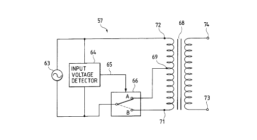
AC Voltaqe Control Circuit
Fig. l shows a circuit arrangement of an AC voltage
control section of the low voltage power supply according to
the present embodiment. An AC power source 63 supplied from
the input terminal 61 shown in Fig. 3 is input to an input
voltage detector 64 within the low voltage power source 57.
2S ~he input voltage detector 64 checks whether an input AC
voltage is above or below 150V. The detector can readily be
1 realized by using an IC package for voltage comparison as
commercially available. In this case, the above voltage is
appropriately formed and applied to the reference voltage
t~rm;n~l of the IC. The input voltage detector 64 produces the
check result in the form of a switching control signal 65l
which is applied as a control signal to a power relay 66. The
power relay 66, coupled with one end of the AC power source 63,
functions to select contact A or contact B according to the
type of the control signal 65. The contact A is connected to
a mid-point 69 of the primary winding of a transformer 68. The
contact B is connected to one end 71 of the winding of the
transformer 68. The other end 72 of the primary winding is
connected to the other end of the AC power source. Both ends
73 and 74 of the secondary winding of the transformer 68 are
coupled with the input te in~ls of the fusing unit 58 shown
in Fig. 3.
When the input voltage detector 64 detects an input
voltage of 150V or less, the power relay 66 selects the contact
A. When it detects an input voltage of more than 150V, the
power relay 66 selects the contact B. If the input AC voltage
is between 90V and 120V, that voltage, as it is, is output from
the secondary winding of the transformer 68. When it is
between 200V and 250V, that voltage is hal~ed into a voltage
between lOOV and 125V, and the halved voltage is output from
the secondary winding of the transformer 68. With this
- 14 -
c~ ~ ~
1 feature, the same ~using unit be used in any region and any
country of the world.
Fig. 4 shows a circuit diagram of a fusing unit used
in the instant embodiment. As shown, the AC input t~rminals 81
and 82 are coupled with both ends 73 and 74 of the secondary
windings of the transformer 68 shown in Fig. 1. A fuse 2,
heater 4, and a solid state relay ~SSR) 84 are connected in
series between those input terminals 81 and 82. The fuse 2 is
in light contact with the heat roller 6 as shown in Fig. 14,
and is broken when the heat roller 6 is over heated.
The surface temperature of the heat roller 6 is also
detected by a thermistor 85. Temperature data 86 as detected
by the thermistor 85 is transferred to a temperature control
unit 87. In the control unit 87, the data is applied through
a data input buffer amplifier 88 to a data processor 89. In
the data processor 89, an A/D converter contained therein
converts the temperature data as analog data into digital data.
A CPU contained forms a temperature control signal 91 which
depends on the surface temperature. The control signal 91
passes through a data output buffer 92, and reaches a control
term;n~ of the SSR. In this way, the current is fed to the
heater. An AC voltage to control the SSR 84 is usually between
90V and 125V. Accordingly, in any region and any country of
the world, the laser printer 11 can optimally control the
surface temperature of the heat roller 6.
- 15 -
S,,.~
1 Modifications
Fig. 5 is a circuit arrangement of a fusing unit as
a modification of the present invention, and its low power
voltage supply. In this modification, a low voltage power
5 supply 57A contains an AC power source 63, input voltage
detector 64 for checking whether the input AC voltage belongs
to a relativel~ high voltage region or a relatively low voltage
region, solid state.relay 84, and a power relay 101. A fuse 2
that is connected in series to the SSR 84, and a heat control
6A are disposed outside the low voltage power supply 57A. A
couple of heaters 4A and 4B that are exactly the same in shape
and characteristic, are contained in the heat roller 6A. The
power relay 101 connects those heaters 4A and 4B selectively in
series or parallel.
To be more specific, first and second switches 102 and
103, that are interlocked wLth each other, are contained in the
power relay 101. In response to the switching control signal
65 from the voltage detector 64, those switches are turned to
contacts A or B. One end of the heater 4A is connected to one
end of the AC powers source 63, by way of the SSR 84 and the
fuse 2. The other end of the heater 4~ is connected to the
ter~;n~l C of the first switch 102. The contact B of the first
switch 102 is connected to the contact B of the second switch
103. The contact A of the second switch 103 is connected to
one end of the heater 4A. The contact A of the first switch
102 is connected to one end of the heater 4B and the other end
- 16 -
2~23369
of the AC power source 63. The terminal C of the second switch
103 is connected to the other end of the heater 4B.
When the input voltage detector 6~ detects a voltage of
150V or less as supplied from the power source 63, the contacts
C are respectively turned to the contacts A in the power relay
101, as indicated by dotted lines. The voltage of the power
source 63 is directly applied to both ends of each heater 4A
and 4B.
When the detector 64 detects the input voltage of
higher than 150V, the contacts C of the power relay 101 are
respectively turned to the contacts B, as indicated by solid
lines. Under this condition, the heaters 4A and 4B are
connected in series, and the voltage of the AC power supply 63
is applied to both ends of the series connection of the
heaters.
Fig. 6 shows a simplified circuit diagram of a key
portion of the circuit of Fig. 5. Fig. 7 shows the simplified
circuit diagram when the heaters 4A and 4B are connected in
parallel. Fig. 8 shows the simplified circuit diagram when the
heaters 4A and 4B are connected in series.
Where the voltage of the AC power source 63 belongs to
the power supply system of lOOV to 115V, for example, the two
heaters 4A and 4B are connected in parallel, as shown in Fig.
7. If those heaters are lamps of 300W, the total power
consumption is approximately 600W. Where it belongs to the
power supply system of 200V to 240V, the two heaters 4A and 4B
- 17 -
1 are connected in series as shown in Fig. 8. Also in this case,
the total power consumption is approximately 600W.
Accordingly, in any region and any country of the world, thè
laser printer 11 can optimally control the surface temperature
of the heat roller 6.
It is noted that the couple of heaters 4A and 4B are
both operated for any vol~age of the AC power source 63, and
one of the heaters is not used as a backup heater, which is
operated when the other is broken. It is further noted that
the heaters 4A and 4B are different from those used in the
fusing unitas described in Japanese Utility Model Un~m;ned
Publication No. Sho. 63-150967. In the publication, one of the
two heaters is heated by the AC power source, while the other
is heated by a battery. Such a precision of the
characteristics of the heaters 4A and 4B in the instant
embodiment as to provide a satisfactory fusing when they are
connected in series and parallel, suffices. In other words, a
variation of resistance of each heater within the range
ensuring such a characteristic precision is tolerable.
Fig. 9 is a longitudinal section view showing a
structural arrangement of the fusing unit according to this
modification, which corresponds to that of Fig. 14. A couple
of heaters 4A and 4B are fastened to check plates 111. The
check plates 111 are fixed to support plates 52 by lamp
supports 5~.
- 18 -
2~23369
Fig. 10 shows the detail of each check plate 111. The
check plate 111 consists of a rectangular metal plate having a
thickness of 0.1 to 0.2mm. The rectangular plate is bent in an
L shape as viewed in cross section, for reinforcing purposes.
The plate having a longer leg of the L shape is cut away in a
T-like shape denoted as 112. Both end portions of the cross
bar of the T are opened and each opening is shaped circularly.
A pair of pawls 114 protrude in opposite directions from each
circular opening. When the check plates 111 are too thick,
they cannot satisfactorily fix the heaters 4A and 4B in place.
When made too thick, the heaters 4A and 4B tend to be scraped
by the pawls 114 when they are mounted to the check plates 111.
Fig. 11 shows a side view of the structure when a base
portion of the heater is mounted to the check plate 111. A
base portion 122 of the heater 4A (4B) as the end portion of a
quartz tube, is tubular and has a collar 121. An insulated
wire 123 is connected to a resistor wire contained in the
quartz tube at one end of the base portion 122. When
assembling the laser printer 11, a worker directs the forward
end of the bent portion 124 of the check plate 111 toward the
center of each heater, inserts the insulating wire 123 into the
cutaway portion 112 shown in Fig. 10, and thrusts the forward
end of the base portion 122 into the opening 113 ~see Fig. 10)
until the collar 121 comes in contact with the check plate 111.
At this time, the paired pawls 114 are in press contact with
the circumferential sur~ace of the base portion 122 and are
- 19 -
2~23369
forcibly bent forward. In this way, the heaters 4A and 4B are
fastened to the check plate 111. Since two check plates 111
are provided at the right and left ends of the heaters, the
above fastening work is applied to both ends o~ the heaters 4A
and 4B.
Fig. 12 is a diagram showing the structure when both
heaters are fastened to the check plate in the above manner.
The heaters 4A and 4B are fastened in parallel to the check
plate 111, while care is taken so as to avoid mutual contact of
the quartz tubes of the heaters. Since the two heaters 4A and
4B are fixed by the check plates 111, the work of assembling
those components into the heat roller 6 can be done smoothly
and easily.
Recently, the image forming apparatus of the electro-
photographic type including the laser printer has become
smaller and smaller. Accordingly reducing the size of the heat
roller has also been required. Therefore, one would ~e lead to
believe that an effective approach is to bond together the
tubular members of the heaters, such as the quartz tubes, and
to provide the base portions in a single base portion.
However, such an approach requires a great alternation of the
manufacturing process of the lamp type heaters. The cost to
manufacture the heaters is increased and reliability of the
resultant heaters is impaired. In this regard, it is best to
space the two heaters 4A and 4B.as close together as possible.
_ 20 -
Returning to Fig. 9, each support plate 52 supports
each collar 61 of the heat roller 6, with each bearing 53
interposed therebetween. A gear 62 fixed to one end of the
- heat roller 6 is in mesh with a gear (not shown). The heat
roller 6 receives a motive power through the gear chain, and
rotates at a predetermined speed. A. fuse 63 and the thermistor
85 slightly contact with the surface of the heat roller 6, to
monitor temperature on the surface. A connector 131 with three
pins accommodates insulating wires 123l and 1232 as derived from
the first ends of the heaters 4A and 4B, and an insulating wire
1233 connected to a t~ in~l 132~ mounted to one end of the fuse
63. ~ connector 133 with two pins accommodates an insulating
wire which is connected to an insulating wire 1234 connected to
a te in~l 132~ mounted on the other end of the fuse 63, and an
insulating wire 1235 derived from the other end of the heater
4A, and an insulating wire 1236 derived from the other end of
the heater 4B. The two connectors 131 and 133 are used for
connecting the low voltage power supply 57A (see Fig. 5) to the
external components.
The heat roller 6 is in press contact with the pressure
roller 8 that is rotatably supported by a couple of bearings
135. The press contact extends over a predetermined width of
the rollers, to form a nip region. Record paper (not shown)
passes through the nip region. When passing there, it is
heated by the two heaters 4A and 4B and a toner image formed
thereon is fused and fixed.
-- 21 --
.~
2023~69
While the pair of heaters 4A and ~B operable by the AC
voltage are described, four more hea~ers may be used. It is
evident that the present invention is applicable for any other
electric components consuming relatively larger power than the
heaters.
It is further evident that the present invention, which
has been applied to the la'ser printer in the above-mentioned
embodiment, is applicable for other image forming apparatuses,
such as copying machines and facsimiles.
According to the present invention, input AC voltages
are classified into two groups by comparing the input AC
voltages with a reference voltage. An input AC voltage, which
is higher than the reference voltage, is substantially halved
and the halved voltage is used. Another input AC voltage,
which is lower than the reference voltage, is used as it is.
The AC components are operable regardless of the input AC
voltage. Accordingly, the cost for the AC components can be
reduced.
Further, a couple of heaters with substantially the
same characteristics are used, which are to be coupled for
reception with an AC input voltage. In use, the heaters are
connected selectively in series or in parallel, and therefore,
there is no need for the voltage adjusting transformer. This
leads to reduce cost in manufacturing the apparatus.
Having described the preferred embodiments of the
present invention it will be understood that modifications and
- 22 -
20233G9
variations thereof falling within the spirit and scope of the
invention may become apparent to one skilled in the art and
that the scope of the invention is to be determined by the
appended claims and their equivalents.