Note : Les descriptions sont présentées dans la langue officielle dans laquelle elles ont été soumises.
Lo O G3~
The invenLion relates to a method for removing impurities from paper
pulp in pulpers wherein the pulping space, whereto the paper pu1p to be
purified is conducted, is provided with a rotor unit or the like and a
screenplate associated therewith.
Prior art methods and apparatus are described for instance in
publications FI-74496, DE-3 639 200 and EP-279 022. The methods and
apparatus described in these publications involve a separate wash space
associated with the pulping space and which is relatively small in volume
compared to that of the pulping space. Therefore, these prior art methods
and apparatus need separate attachments to be connected to the actual
pulping space. Handling of the rejected portion is particularly difficult
and these methods require a substantial amount of wash water. The capacity
of such methods is low and some of them involve batch operation.
The object of the present invention is to present a method by which it
is possible, while maintaining an undisturbed operation, to remove
especially the very light impurities from paper pulp in the most efficient
way and at the same time keep fiber losses low so that the capacity for
removal of impurities remains high.
Thus, according to the present invention, there is provided a novel
method for removing impurities from paper pulp in a pulper and a novel
apparatus for practising said method. The pulper is provided with apparatus
including an enclosed pulping space divided into a primary space and a
secondary space by means of a partition wall construction. Means are
provided enabling communication between the primary space and secondary
space and each of said primary and secondary spaces is provided with a
respective rotor means and screening means associated with the rotor means.
Paper pulp to be purified is conducted into the primary space.
Thus, the novel method of this invention can be used in connection with
either new or existing pulper constructions, the method in the latter case
having no detrimental influence on the pulping time. The apparatus for
practising this novel method has high capacity and its volume can be
dimensioned according to the purification requirements. Also, it can be
designed to efficiently prevent the large heavy impurities from entering the
screenplate in the secondary space and efficiently collect the light
impurities. The invention also makes it possible to increase the bale
submerging efficiency.
-- 1 --
PAT 15971-1
2~3~3
The pulping efficiency increases since there are provided two rotor
units in the pulping space and the power consumption per unit mass of paper
pulp to be screened is thereby decreased compared to prior art devices.
The novei apparatus can easily be designed to have such a form that the
exiting accepted portions (the "accepts") can be jointly conducted forwardly
to the following processing stage and so there is no need for recycling
which decreases the capacity.
Since the t:otal area of the screening surfaces or the like can be made
large, it is possible to use a smaller hole size and thereby achieve a purer
paper pulp to be conducted forward to the next processing stage.
Expensive and large automatic valves are not needed in this invention,
makin8 the process control cheaper and simpler.
Removal of the accepts from the secondary space can be done either
periodically or continuously, e.g., by means of a screw conveyor.
The outlet consistency of the rejected portion ("rejects") removed from
the secondary space can exceed 20~, so that the subsequent processing of the
rejects or removal from the pulping process (for instance, for use in
ballasting or in combustion) can be simply realized, e.g., by means of belt
conveyors. It is possible to wash rejects in the screw conveyor permitting
complete collection of fibers using small amounts of water; and the accepts
filtered in the screw conveyor can be conducted to the main pump and
forwardly in the process.
The invention does not disturb the automation of the rotor unit
functioning as the actual pulper in the primary space and does not produce
any major consistency variations to the main pump.
The invention a]lows conduction of a major part of the paper pulp
through the secondary space, if necessary, and impurities are conducted into
the secondary space, thus making it unnecessary to stop the rotor unit for
cleaning the screenplate in the primary space, which functions as the actual
pulping space.
Other beneficial applications according to the method and apparatus of
the invention will hereinafter become apparent.
The invention will now be described further by way of example only and
with reference to the accompanying drawings, wherein:
Figures 1 and 2 illustrate apparatus according to the invention, shown
in vertical cross-section.
-- 2 --
PAT 15971-1
I-``` 2~3&~3
Figure 3 shows the apparatus of Figures 1 and 2 in horizontal
cross-section seen from above.
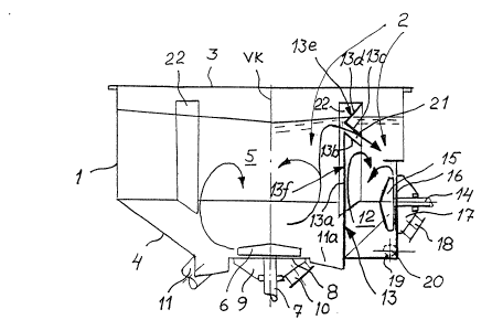
The embodiment of Figures 1 - 3 comprises a pulping space 2 enclosed by
a solid jacket 1. As seen particularly in Figure 3, the jacket 1 of the
pulping space 2 is essentially circular in horizontal cross-section.
Furthermore, the vertically disposed cylindrical jacket 1 contains an upper
end portion 3 on one hand and on the other hand a lower end portion 4, which
in the horizontal direction essentially defines the pulping space 2.
The paper pulp to be purified is introduced into the pulping space 2
from the side of the upper end portion 3 (not shown) into the primary space
5 accommodating a horizontally rotating rotor unit 6 adjacent the lower end
portion 4, the rotor unit 6 having a vertical drive shaft 7, which is
parallel with the center line VK of the jacket and arranged to rotate about
said center line VK and which passes through the lower end portion 4. Under
the rotor unit 6 there is provided a perforated horizontal screenplate 8
through which there is a connection from the primary space S into the
accepts outlet chamber 9 below the rotor unit 6 and the screenplate 8, the
outlet chamber 9 having an accepts outlet connection 10. Furthermore, in
the lower end portion 4 there is provided an annular groove lla surrounding
the rotor unit having at its lowest portion the rejects outlet connection 11.
The pulping space 2 is also provided with a secondary space 12 by means
of a vertical partition wall construction 13 dividing the pulping space 2.
The secondary space 12 accommodates a corresponding rotor unit 15 arranged
to rotate in a vertical plane about a horizontal shaft 14. The jacket 1 has
in the proximity of the rotor unit 15 a perforated vertical screenplate 16
through which there is provided a connection from the secondary space 12 via
the rotor unit 15 into the outlet chamber 17 for the accepted portion of the
secondary space 12, the outlet chamber 17 having an accepts outlet
connection 18. There is also a rejects outlet connection 19 in the lower
part of the secondary space 12 and a screw conveyor 20 or the like is
mounted in contact with the outlet connection 19 of the secondary space 12
for removing the rejected portion from the secondary space.
As can be seen in Figures 1 - 3, the primary space 5 is larger in
volume than the secondary space 12, this being due to the disposition of the
PAT 15971-1
23~.3
partition wall construction 13. In horizontal cross-section, the partition
wall construction divides the upper cross-section of pulping space 2 (Figure
3) into two segments, the larger one constituting the primary space 5 and
the smaller one the secondary space 12.
The partition wall construction 13 can be a plate structure attached by
its vertical sides to the inner walls of the pulping space 2. The plate
structure can be partly or wholly perforated so that there will be flow of
the paper pulp to be purified through the perforations from the primary
space 5 into the secondary space 12. Furthermore, the upper region of the
partition wall construction 13 in proximity to the surface of the paper pulp
may have a flow channel 21 extending downwardly towards the secondary space
12 as illustrated particularly in Figure 1, especially for conducting the
lighter impurities into the secondary space 12. The flow channel 21 is
formed by means of an upper guide plate 13b, disposed on the upper edge of
the vertical plate 13a of the lower part 13f of the partition wall
construction 13 and being directed obliquely downwards from said upper edge
towards the secondary space 12, and a lower guide plate 13c disposed on the
upper part 13e of the partition wall structure 13, the plate 13c located
above the plate 13b and spaced therefrom to form the channel 21. The lower
guide plate 13c, which is essentially parallel with the plate 13b in
vertical cross-section (Figure 1), is joined by its horizontal edge facing
the primary space 5 to the plate 13d, which is directed obliquely upwards
away from the primary space 5, the plate 13d thus forming the upper part 13e
of the partition wall structure 13 together with the plate 13c. The upper
edge of the partition wall construction 13 is located below the inner
surface of the upper end portion 3 at a distance therefrom.
As may be seen particularly in Figures 1 and 3, the inner surfaces of
the jacket 1 in the pulping space 2 are equipped with essentially vertical
flow guide vanes 22 (four of them with a specific spacing).
The embodiment of the apparatus shown in Figures 1 - 3 functions in the
following ways. Paper pulp is supplied (e.g. in bales) into the primary
space 5 where the bales break down and are simultaneously mixed with water,
which is supplied into the primary space 5 (not shown). In the primary
space 5, a rotary motion is created by the rotor unit 6 and the accepted
PAT 15971-1
2 3
portion is moved by the blades of the rotor unit 6 through the perforations
of the screen plate 8 into the accepts outlet chamber 9 and therefrom to the
outlet connection 10 which is connected to, for example, a pulp vat to which
the pulp is pumped by means of a pump attached to a pipe in the outlet
connection 10. The rejection portion, draining away through the outlet
connection 11 of the primary space 5, is treated after its exit through the
outlet connection by means of high pressure water in order to return the
possibly usable fibers in the rejected portion for recycling. The paper
pulp going into the secondary space 12 through the partition wall
construction 13 is driven into a rotary motion by the influence of the rotor
unit 15 in the secondary space and the blades of the rotor unit 15 move the
accepted portion through the perforations of the screenplate 16 into the
accepts outlet chamber 17 and further into a pipe connected to the accepts
outlet connection 18 wherefrom it is pumped into a pulp vat. In the
processing of the rejected portion, which has been removed from the bottom
of the secondary space by means of a screw conveyor or the like, high
pressure water is used for separating the possibly usable fibers still in
the rejecled portion.
PAT 15971-1