Sélection de la langue

Search

Sommaire du brevet 2024271 

Énoncé de désistement de responsabilité concernant l'information provenant de tiers

Une partie des informations de ce site Web a été fournie par des sources externes. Le gouvernement du Canada n'assume aucune responsabilité concernant la précision, l'actualité ou la fiabilité des informations fournies par les sources externes. Les utilisateurs qui désirent employer cette information devraient consulter directement la source des informations. Le contenu fourni par les sources externes n'est pas assujetti aux exigences sur les langues officielles, la protection des renseignements personnels et l'accessibilité.

Disponibilité de l'Abrégé et des Revendications

L'apparition de différences dans le texte et l'image des Revendications et de l'Abrégé dépend du moment auquel le document est publié. Les textes des Revendications et de l'Abrégé sont affichés :

  • lorsque la demande peut être examinée par le public;
  • lorsque le brevet est émis (délivrance).
(12) Brevet: (11) CA 2024271
(54) Titre français: INTERFACE A FIBRES OPTIQUES
(54) Titre anglais: OPTICAL FIBER INTERFACE
Statut: Réputé périmé
Données bibliographiques
(51) Classification internationale des brevets (CIB):
  • G02B 6/35 (2006.01)
  • G02B 6/42 (2006.01)
  • H04B 10/12 (2006.01)
  • H04B 10/08 (2006.01)
(72) Inventeurs :
  • HUGHES, RICHARD PIERRE (Canada)
  • SO, VINCENT CHOONG (Canada)
  • VELLA, PAUL JOSEPH (Canada)
(73) Titulaires :
  • NORTEL NETWORKS LIMITED (Canada)
(71) Demandeurs :
  • HUGHES, RICHARD PIERRE (Canada)
  • SO, VINCENT CHOONG (Canada)
  • VELLA, PAUL JOSEPH (Canada)
(74) Agent:
(74) Co-agent:
(45) Délivré: 1997-12-30
(22) Date de dépôt: 1990-08-29
(41) Mise à la disponibilité du public: 1991-04-27
Requête d'examen: 1993-07-28
Licence disponible: S.O.
(25) Langue des documents déposés: Anglais

Traité de coopération en matière de brevets (PCT): Non

(30) Données de priorité de la demande:
Numéro de la demande Pays / territoire Date
426,659 Etats-Unis d'Amérique 1989-10-26

Abrégés

Abrégé anglais


An optical fiber interface includes a detector assembly,
which may include an integral fiber, for detecting an optical signal
carried on a single fiber in an outbound direction and a piezo
electric transducer or the like for providing relative movement
between the fiber and the detector assembly to produce a modulated
return optical signal in reflections of the outbound signal. The
return optical signal has a lower frequency or data rate than the
outbound signal. Several embodiments modulate the return signal by
relative movement either perpendicular to or parallel to the fiber.
The perpendicular movement modulates the reflected signal by varying
alignment of the fiber and detector assembly, while the parallel
movement modulates by varying a Fabry-Perot gap formed between the
fiber and the detector assembly. One embodiment includes a cantilever
beam of semiconductor material attached to the detector surface. The
beam providing an integrated transducer and reflecting surface.

Revendications

Note : Les revendications sont présentées dans la langue officielle dans laquelle elles ont été soumises.


WHAT IS CLAIMED IS:

1. An optical fiber interface, comprising:
an optical fiber;
means for continuously monitoring modulated light carried
in a first direction by the fiber; and
means responsive to an electrical signal for effecting
relative movement between the fiber and the monitoring means to
modulate reflected light carried in a second direction, opposite to
the first direction, by the fiber.

2. An interface as claimed in claim 1 wherein the
relative movement is directed parallel to a longitudinal axis of the
fiber.

3. An interface as claimed in claim 1 wherein the
relative movement is directed perpendicular to a longitudinal axis of
the fiber.

4. An interface as claimed in claim 2 wherein the
relative movement is effected by displacing the fiber.

5. An interface as claimed in claim 2 wherein the
relative movement is effected by displacing the monitoring means.

6. An interface as claimed in claim 3 wherein the
relative movement is effected by displacing the fiber.

7. An interface as claimed in claim 3 wherein the
relative movement is effected by displacing the monitoring means.

8. An interface as claimed in claim 4 wherein the
monitoring means comprises a second optical fiber and a detector means
coupled thereto, the first and second optical fibers forming a
Fabry-Perot gap, wherein the relative movement means is adapted for
effecting a displacement of the first fiber for varying the
Fabry-Perot gap.


9. An interface as claimed in claim 5 wherein the
monitoring means comprises a second optical fiber and a detector means
coupled thereto, the first and second optical fibers forming a
Fabry-Perot gap, wherein the relative movement means is adapted for
effecting a displacement of the first fiber for varying the
Fabry-Perot gap.

10. An interface as claimed in claim 5 wherein the
monitoring means comprises a detector and a beam member between the
fiber and the detector, the beam member having a partially reflecting
surface, wherein the relative movement means is adapted for effecting
an angular displacement of the beam member between first and second
positions, in which, respectively, first and second amounts of light
reflecting from the surface of the beam member are incident upon an
end surface of the fiber, the first amount of light being greater than
the second amount.

11. An interface as claimed in claim 6 wherein the
relative movement means is adapted for effecting an angular
displacement of an end portion of the optical fiber between a first
position in which a first amount of light reflecting from the surface
of the monitoring means is incident upon the end surface of the
optical fiber, and a second position in which a second amount of light
reflecting from the surface of the monitoring means is incident upon
the end surface of the optical fiber, the first amount of light being
greater than the second amount.

12. An interface as claimed in claim 6 wherein the
relative movement means is adapted for bending the optical fiber
between a first position in which an amount of light carried in the
fiber is attenuated, and a second position in which a greater amount
of light carried in the fiber is attenuated.

13. An interface as claimed in claim 6 wherein the
monitoring means comprises a second optical fiber and a detector means
coupled thereto, wherein the relative movement means is adapted for


effecting a displacement of the fiber between a first position in
which an amount of light exiting one fiber enters the other fiber, and
a second position in which a lesser amount of light exiting one fiber
enters the other fiber.

14. An interface as claimed in claim 7 wherein the
monitoring means comprises a second optical fiber and a detector means
coupled thereto, wherein the relative movement means is adapted for
effecting a displacement of the fiber between a first position in
which an amount of light exiting one fiber enters the other fiber, and
a second position in which a lesser amount of light exiting one fiber
enters the other fiber.

15. An interface as claimed in claim 10 wherein the
relative movement means comprises the beam member consisting
essentially of semiconductor material attached at one of its ends to
the detector thereby to form a cantilever.

16. An interface as claimed in claim 8, 9, or 11 wherein
the relative movement means comprises a piezo electric device.

17. An interface as claimed in claim 12, 13, or 14
wherein the relative movement means comprises a piezo electric device.

18. An interface as claimed in claim 8, 9, or 11 wherein
the relative movement means comprises a electromechanical device.

19. An interface as claimed in claim 12, 13, or 14
wherein the relative movement means comprises a electromechanical
device.

Description

Note : Les descriptions sont présentées dans la langue officielle dans laquelle elles ont été soumises.


2~24271

OPTICAL FIBER INTERFACE
This invention relates to an optical fiber interface, and
is particularly concerned with such interfaces for converting between
electrical signals and optical signals on an optical fiber for use at
a subscriber's premises in a telecommunications network.
It has been proposed to use optical fibers for connecting
subscribers to telecommunications networks, thereby expanding the
range of services available to subscribers especially as a result of
much larger bandwidths being available than are available using
existing copper subscriber lines. However, optical fiber subscriber
connections may involve higher costs. For example, an optical fiber
interface for subscriber lines may require costly components such as a
light source, a coupler and a receiver, in contrast to copper line
interfaces which cost very little. It would be desirable to provide
an optical fiber interface which uses fewer and less expensive
components, and which also requires a minimum of setup.
In Ettenberg et al. U.S. Patent No. 4,195,269 dated March
25, 1980 and entitled "Two-Way Communication System", a two-way single
fiber optical communication system is disclosed in which optical
couplers at both ends of an optical fiber link are eliminated, and a
light source is required at only one end of the link.
An object of the present invention is to provide an
improved optical fiber interface.
In accordance with the present invention there is
provided an optical fiber interface comprising: an optical fiber;
means for continuously monitoring modulated light carried in a first
direction by the fiber; and means responsive to an electrical signal
for effecting relative movement between the fiber and the monitoring
means to modulate reflected light carried in a second direction,
opposite to the first direction, by the fiber.
In an embodiment of the present invention the means for
movement effects a displacement of the fiber directed parallel to a
longitudinal axis of the fiber.
In another embodiment of the present invention the means
for movement effects a displacement of the monitoring means directed
parallel to a longitudinal axis of the fiber.

2024271

In a third embodiment of the present invention the means
for movement effects a displacement of the fiber directed
perpendicular to a longitudinal axis of the fiber.
In a fourth embodiment of the present invention the means
for movement effects a displacement of the monitoring means directed
perpendicular to a longitudinal axis of the fiber.
The present invention will be further understood from the
following description with reference to the drawings, in which:
Figs. 1 to 4 schematically Illustrate different
embodiments of the present invention.
Similar references are used in different figures to
denote similar components.
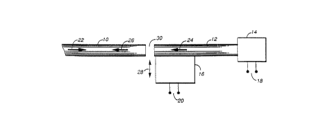
Referring to Fig. 1, an optical fiber interface is shown
which includes a first optical fiber 10, a second short optical fiber
12 aligned with and spaced from the first fiber 10 at a first end and
coupled at a second end to an optical signal detector 14 having an
electrical signal output 18, and a piezo electric transducer 16,
having an electrical signal input 20. The optical fiber 12 is
attached adjacent its first end to an upper surface of the piezo
electric transducer 16, which is responsive tG a signal supplied to
its input 20 to move the fiber 12 in the direction of an arrow 28,
that is perpendicularly to the axis of the fiber 12, between the
al7gned position shown and a slightly offset or misaligned position.
In operation, an optical signal, typically modulated at a
bit rate of 45 Mb/s or more, is supplied in a first direction,
represented by an arrow 22, via the fiber 10. With the fiber 12 in
the aligned position, this optical signal traverses a gap 30 between
the aligned fibers 10 and 12 and is supplied via the fiber 12 to the
detector 14, where it is detected to produce 2 corresponding
electrical signal at output 18. A portion of the light reaching the
detector is reflected by the detector and provides a returned optical
signal in the fiber 12, represented by an arrow 24, which passes via
the gap 30 to fiber 10, as represented by an arrow 26. A potential
difference applied to the input 20 of the piezo electric transducer 16
causes a misalignment of fibers 10 and 12, the degree of misalignment
being dependent upon the amplitude of the potential difference and
serving to control the amount of the reflected light which reaches and

202~271

is returned by the fiber 10. A signal applied to the input 20 thus
amplitude modulates a returned optical signal; such a modulation can
have a frequency or bit rate which is one or more orders of magnitude
smaller than the bit rate of the signal supplied in the direction 22
5 via the fiber 10.
Obviously, the fiber 10 could, instead of fiber 12, be
attached to the piezo transducer 16, with similar results. In either
case, however, there is a disadvantage in that the amount of the
supplied optical signal reaching the detector 14 is also affected by
the fiber misalignment. In other words, the modulation depth of the
returned signal is only enhanced at the expense of higher insertion
loss of the interface.
This disadvantage is reduced by the alternative
arrangement shown in Fig. 2, in which the transducer 16 is responsive
to a signal applied to its input 20 to move fiber 12 in a direction 29
parallel to the aligned axes of the fibers 10 and 12, thereby to vary
the width of a Fabry-Perot gap 40 between the fibers.
In a first position, light reflected at the first end 34
of the fiber 10 and light reflected at an adjacent end 32 of the fiber
12 are in phase and add together to produce a returned optical signal
in the direction 26. In a second position, the light reflections from
the two ends 32 and 34 are 180 degrees out of phase and cancel each
other to produce substantially no returned optical signal. Hence, the
Fabry-Perot gap 40 between the ends 32 and 34 is varied by the
25 electrical signal applied to the input 20 to effect modulation of the
amplitude of the returned optical signal.
For uncoated glass-air interfaces at the ends 32 and 34
each light reflection is about 4%, so that the total return signal
level is about 8% of the amplitude of the optical signal supplied in
30 the directinn 22. As in the case of Fig. 1, the transducer 16 can
instead be arranged to move the fiber 10.
The disadvantage of enhancing modulation depth at the
expense of higher insertion loss of the interface is also reduced in a
third embodiment of the present invention as shown in Fig. 3, in which
35 an optical fiber 10 is attached to an upper surface of a transducer
16, such that the end 34 of the fiber extends beyond an edge of the
transducer to form a cantilever of length 42. The optical fiber 10 is

202~271

set up with its axis perpendicular to a surface 44 of the detector 14
and approximately aligned with the center of the detector surface 44.
In a first position light is reflected from the detector
surface 44 and provides a returned optical signal, in a direction 24,
which enters fiber 10 in a direction 26. Movement of the fiber in a
direction 28 causes both a displacement and flexing of the
cantilevered end of the fiber 10 such that at a second position, the
end of the fiber 10 is flexed to a sufficient degree to prevent light
entering the fiber 10 thereby to produce substantially no returned
optical signal 24. Hence, the position of the fiber is varied by an
electrical signal applied to the input 20 to effect modulation of the
amplitude of the returned optical signal.
A fourth embodiment of the present invention provides a
further reduction in the number of components and setup requirements.
As shown in Fig. 4, the transducer 16 of the previous embodiments is
replaced by a transducer 50, comprising a beam 52 cantilevered by
attachment at an end 54 to the face 58 of detector 14, and having
input 20. The transducer 50 uses an upper semiconductor layer of
detector 14 for one of its input terminations as denoted by broken
line in Fig. 4. The axis of fiber 10 is aligned to be perpendicular
to and approximately centered with the surface 60 of beam 52.
When no voltage is applied to input 20, the beam 52
remains approximately parallel to the face 58 of detector 14. The
application of a voltage to input 20 produces an electrostatic force
between the beam 52 and the face 58 causing an angular displacement of
beam 52. With the beam 52 in a first position, light reflected at the
surface 60 enters the fiber 10 via the fiber end 34 to produce a
returned optical signal in a direction 26. In a second position an
end 56 of the beam 52 is displaced such that the light is reflected
away from the fiber end 34 to produce substantially no returned
optical signal. Hence, the relative angle between the axis of fiber
10 and the face 60 of beam 52 is varied by the electrical signal
applied to the input 20 to effect modulation of the amplitude of the
returned optical signal.
Although a piezo device has been described in three of
the specific embodiments of the present invention, a suitable

202~271

electromechanical device having the required frequency response, can
be substituted.
The present invention provides an optical fiber interface
which uses a few inexpensive components and requires little setup.
Numerous modifications, variations and adaptations may be
made to the particular embodiments of the invention described above
without departing from the scope of the invention, which is defined in
the claims.


,


- 35


~ .

Dessin représentatif
Une figure unique qui représente un dessin illustrant l'invention.
États administratifs

Pour une meilleure compréhension de l'état de la demande ou brevet qui figure sur cette page, la rubrique Mise en garde , et les descriptions de Brevet , États administratifs , Taxes périodiques et Historique des paiements devraient être consultées.

États administratifs

Titre Date
Date de délivrance prévu 1997-12-30
(22) Dépôt 1990-08-29
(41) Mise à la disponibilité du public 1991-04-27
Requête d'examen 1993-07-28
(45) Délivré 1997-12-30
Réputé périmé 2007-08-29

Historique d'abandonnement

Il n'y a pas d'historique d'abandonnement

Historique des paiements

Type de taxes Anniversaire Échéance Montant payé Date payée
Le dépôt d'une demande de brevet 0,00 $ 1990-08-29
Enregistrement de documents 0,00 $ 1991-06-28
Taxe de maintien en état - Demande - nouvelle loi 2 1992-08-31 100,00 $ 1992-07-15
Taxe de maintien en état - Demande - nouvelle loi 3 1993-08-30 100,00 $ 1993-06-02
Taxe de maintien en état - Demande - nouvelle loi 4 1994-08-29 100,00 $ 1994-06-08
Taxe de maintien en état - Demande - nouvelle loi 5 1995-08-29 150,00 $ 1995-07-19
Taxe de maintien en état - Demande - nouvelle loi 6 1996-08-29 150,00 $ 1996-08-07
Taxe finale 300,00 $ 1997-08-06
Taxe de maintien en état - Demande - nouvelle loi 7 1997-08-29 150,00 $ 1997-08-06
Taxe de maintien en état - brevet - nouvelle loi 8 1998-08-31 150,00 $ 1998-05-27
Taxe de maintien en état - brevet - nouvelle loi 9 1999-08-30 150,00 $ 1999-07-16
Enregistrement de documents 0,00 $ 2000-02-02
Taxe de maintien en état - brevet - nouvelle loi 10 2000-08-29 200,00 $ 2000-05-18
Taxe de maintien en état - brevet - nouvelle loi 11 2001-08-29 200,00 $ 2001-07-19
Taxe de maintien en état - brevet - nouvelle loi 12 2002-08-29 200,00 $ 2002-08-15
Enregistrement de documents 0,00 $ 2002-10-30
Taxe de maintien en état - brevet - nouvelle loi 13 2003-08-29 200,00 $ 2003-07-23
Taxe de maintien en état - brevet - nouvelle loi 14 2004-08-30 250,00 $ 2004-07-27
Taxe de maintien en état - brevet - nouvelle loi 15 2005-08-29 450,00 $ 2005-07-20
Titulaires au dossier

Les titulaires actuels et antérieures au dossier sont affichés en ordre alphabétique.

Titulaires actuels au dossier
NORTEL NETWORKS LIMITED
Titulaires antérieures au dossier
BELL-NORTHERN RESEARCH LTD.
HUGHES, RICHARD PIERRE
NORTEL NETWORKS CORPORATION
NORTHERN TELECOM LIMITED
SO, VINCENT CHOONG
VELLA, PAUL JOSEPH
Les propriétaires antérieurs qui ne figurent pas dans la liste des « Propriétaires au dossier » apparaîtront dans d'autres documents au dossier.
Documents

Pour visionner les fichiers sélectionnés, entrer le code reCAPTCHA :


Pour visualiser une image, cliquer sur un lien dans la colonne description du document. Pour télécharger l'image (les images), cliquer l'une ou plusieurs cases à cocher dans la première colonne et ensuite cliquer sur le bouton "Télécharger sélection en format PDF (archive Zip)" ou le bouton "Télécharger sélection (en un fichier PDF fusionné)".

Liste des documents de brevet publiés et non publiés sur la BDBC .

Si vous avez des difficultés à accéder au contenu, veuillez communiquer avec le Centre de services à la clientèle au 1-866-997-1936, ou envoyer un courriel au Centre de service à la clientèle de l'OPIC.


Description du
Document 
Date
(yyyy-mm-dd) 
Nombre de pages   Taille de l'image (Ko) 
Abrégé 1994-03-31 1 24
Page couverture 1994-03-31 1 14
Revendications 1994-03-31 3 102
Dessins 1994-03-31 2 41
Description 1994-03-31 5 201
Page couverture 1998-01-05 1 54
Dessins représentatifs 1998-01-05 1 4
Dessins 1997-04-22 1 26
Correspondance 2000-02-08 1 22
Cession 2000-01-06 43 4 789
Taxes 1999-07-16 1 34
Correspondance 1997-10-22 2 21
Correspondance 1997-10-22 1 1
Taxes 2002-08-15 1 35
Taxes 2001-07-19 1 36
Taxes 1997-08-06 3 76
Cession 2000-08-31 2 43
Correspondance de la poursuite 1993-07-28 1 25
Correspondance reliée au PCT 1997-08-06 4 122
Correspondance de la poursuite 1996-12-04 2 56
Correspondance de la poursuite 1993-08-17 1 32
Lettre du bureau 1993-08-09 1 34
Lettre du bureau 1995-08-07 1 15
Lettre du bureau 1995-08-07 1 18
Demande d'examen 1996-08-16 1 51
Correspondance 2007-02-07 2 185
Taxes 1996-08-07 1 37
Taxes 1995-07-19 1 31
Taxes 1994-06-08 1 28
Taxes 1993-06-02 1 22
Taxes 1992-07-15 1 26