Note : Les descriptions sont présentées dans la langue officielle dans laquelle elles ont été soumises.
:
202~0~1
1 20375-671
KEY TELE~HONE SYSTEM
BACKGROUND OF THE INVENTION
This invention relates to lmprovement of the
loudspeaking function of key telephone system.
BRIEF DESCRIPTION OF THE DRAWINGS
Figure 1 is a block diagram of configuration of the
prior art,
Figure 2 is a block diagram of a configuration showing a
preferred embodiment of the key telephone system according to the
invention, and
Figure 3 shows comparison of switching characteristics
of the speech signal transmission state and the speech signal
reception state of the embodiment shown in Figure 2 and the
example of prior art in Figure 1.
Figure 1 shows configuration of a key telephone
according to the prior art. A block designated reference number 1
is a main apparatus which is connected to a plurality of key
telephones 21 - 2n through two-wire speech signal lines 31 ~ 3n
and through two-wire control signal lines 41 ~ 4n. In the main
apparatus, the speech signal lines 31 ~ 3n are connected through
speech signal transformers 51 ~ 5n' two/four wire converæion
circuits 61 - 6n and CODECs 71 ~ 7n to a time switch 8. Also, the
control signal lines 41 ~ 4n are connected through control signal
transformers 91 ~ 9n and two/four wire conversion circuits 101 -
10n to a control circuit 11. The time switch 8 performs speech
path switching under control of the control circuit 11.
In the key telephone 2, the speech signal line 3 is
connected through a speech signal transformer 12 and a two/four
~, 202~071
la 20375-671
.. : wire conversion circuit 13 to mode selector switches 1~ and 15.
, ,
~ The mode selector switches 14 and 15 select a handset conversation
. ,,
:~ mode or a loudspeaking conversation mode. When contacts a of the
; .~.
., switches are on, the handset conversation mode is selected. In
,, the handset conversation mode, a handset 16 is connected to the
:
.. two/four wire conversion circuit 13 through a received speech
'. signal amplifier 17 and a transmitted speech signal amplifier 18.
. On the other hand, in the loudspeaking conversation mode in which
.' contacts b are on, a loudspeaking circuit 19 is connected to the
:'.
'~ 10 two/four wire conversion circuit 13. Received speech signals from
. . .
:., the two/four wire conversion circuit 13 are sent through a
....
received voice switching circuit 20 and a speaker amplifier 21 to
.. ~ a speaker 22, and transmitted speech signals from a microphone 23
~ are sent through a
. .
. ~
,;,~
.
.
:
~ .,
;,
.;~
.~;
~3
: .
.. , .. , . , ~ ~, , . ~. -
;,:~ , . ~ ;
.: . : : : , ~
~. .: ~ , . : - ,.. .
.
s;a7;l
....
microphone amplifier 24 and a transmitted voice switching
circuit 25 to the two/four wire conversion circuit 13.
At the same time, the levels of the received speech
signals and transmitted speech signals are detected with
~i 5 a received speech detector 26 and a transmitted speech
, detector 27, respectively, and then supplied to a
~?; comparator 28. The comparator 28 compares the received
~'~r speech signal level, the transmitted speech signal level
and a voltage level from a voltage setter 29, and
according to the comparison results of the three levels,
reciprocally changes losses of the received voice
~; switching circuit 20 and the transmitted voice switching
circuit 25. As a result, a loop gain of a closed loop
~, formed by acoustic coupling between the speaker 22 and
the microphone 23 is controlled to be less than 1, and
: howling (oscillation) can be prevented.
;; One of the problems in the prior-art key telephone
system is that the losses of the received voice switching
circuit 20 and the transmitted voice switching circuit 25
; 20 in the loudspeaking conversation mode must be set to be
greater to prevent the howling because there are a
plurality of closed loops which may generate howling.
Assume that, for example, in Fig. 1, conversation is held
between the key telephone 21 in the loudspeaking mode and
:::! 25 another separate key telephone 2n. When the separate
telephone 2n is in the handset conversation mode, there
; are two closed loops which may generate howling. One of
the loops is formed by the following processes: the
~ ! transmitted speech signal from the microphone 231 i5 sent
'~?,''' 30 to the two/four wire conversion circuit 131 and a part of
the sent signal i9 mixed as a side tone with the received
speech signal, and this side tone is sent to the speaker
221, then a part of the side tone is supplied again to
the microphone 231 owing to acoustic coupling. The other
loop is formed through the following processes: the
transmitted speech signal from the microphone 231 is sent
to the two/four wire conversion circuit 6n in the main
!~
:.`: - : : : :
.~,`,: , -. , .. ::
2~ 71
,~.,i
i
apparatus and a part of the sent signal is mixed as a
side tone with the transmitted speech signal from the
telephone 2n~ and this side tone is returned to the
telephone 2nr and then a part of the side tone is fed
-i 5 from the speaker 221 to the microphone 231 again. When
, the accompanying telephone 2n is also in the loudspeaking
conversation mode, further another closed loop is added.
The loop is formed through the following processes: the
transmitted speech signal from the microphone 231 is sent
to the speaker 22n and a part of the sent signals is
supplied to the microphone 23n owing to acoustic
coupling, the signals supplied to the microphone 23n are
- sent to the speaker 221r then a part of the sent signals
is supplied again to the microphone 231.
Because there may be two or more such closed loops
as described above, the losses of the voice switching
circuits 20 and 25 must be set so large that each loop
gain does not exceed 1. As a result, a high voice level
is required for switching between the speech signal
transmission state (where the loss of the received voice
switching circuit 20 is large and the loss of the
transmitted voice switching circuit 25 is small) and the
speech signal reception state (where the loss of the
received voice switching circuit 20 is small and the loss
of the transmitted voice switching circuit 25 is large),
. thus causing the problem of difficulty in transmitting
voices mutually.
SUMMARY OF THE INVENTION
:.
i An object of the invention is to enable loudspeaking
conversation similar to natural conversation by reducing
losses of the voice switching circuits.
The invention provides a key telephone system
comprising a terminal device and a main apparatus which
exchanges speech signals with the terminal device, the
terminal device having a loudspeaking circuit for
providing a predetermined amount of loss to one of first
speech signals selected to be transmitted to the main
., .
;.,.............................. ., -.: ~ -
~. . ..
2025071
'
apparatus and second speech signals received from the
main apparatus to prevent howling in a loudspeaking
conversation mode, said system comprising:
a first communication means provided in the
terminal device, for sending the first speech signals to
the main apparatus through a first channel and receiving
the second speech signals from the main apparatus through
a second channel separated from the first channel;
second communication means provided in the main
;~ 10 apparatus and connected to the first communication means,
for receiving the first speech signals from the first
communication means through the first channel and sending
the second speech signals to the first ~ommunication
means through the second channel;
v 15in the first and second communication means side
. tones between the first and second speech signals not
being generated,
whereby the predetermined amount of the loss
caused by the loudspeaking circuit can be set to less
than a loss which may be required for howling prevention
if the side tones are generated.
; Between the main apparatus and the terminal
device, the first speech signals from the terminal device
and the second speech signals from the main apparatus are
.~,! 25 transmitted through channels separated from each other,
thereby eliminating the two/four wire conversion circuit
as in prior-art system which generates a side tone,
without the closed loop which may cause howling due to
the side tone. Therefore, the losses for the speech
signals to prevent howling in the loudspeaking
conversation mode can be set relatively small. Setting
relatively small losses means that switching between the
speech signal transmission state and the speech signal
reception state can be performed at relatively low speech
signal levels. Consequently, more natural conversation,
that is, loudspeaking conversation close to simultaneous
two-way conversation is realized.
.
~ :, ' . . ' ' :
.: , . .
.:,. . . .. .
.~, . . .
` 2025071
~ 5 20375-671
,:
DESCRIPTION OF PREFERRED EMBODIHENT
i,
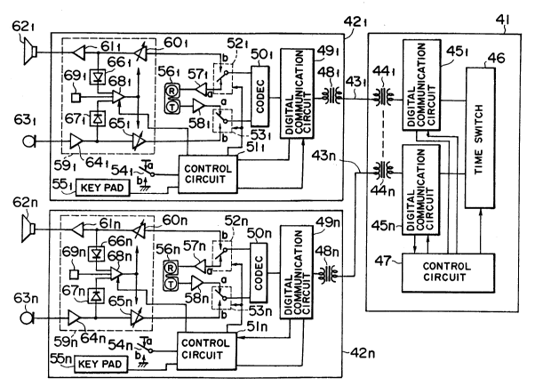
Figure 2 shows a block diagram of configuration of a
~; preferred embodiment according to the invention. In this figure,a
.;:
' block 41 is a main apparatus which is connected to a plurality of
key telephones 421 - 42 through two-wire digital transmission
lines 431 ~ 43n.
~,~ In the main apparatus, the transmission lines 431 ~ 43n
are connected through digital signal transformers 441 ~ 44n to
digital communication circuit 451 ~ 45n' respectively. The
digital communication circuit 451 ~ 45n are connected to a time
switch 46 which performs speech path switching and a control
circuit 47 which controls the speech path switching,and exchange
digital speech signals with the time switch 46 and digital control
signals with the control circuit 47.
In a key telephone 421r by way of example, the
,, transmission line 431 is connected through a digital signal
':~ transformer 481 to a digital communication circuit 491. The
digital communication circuit 491 sends to and receives from the
digital communication circuit 451 in the main apparatus, using a
kind of half-duplex communication system called "Ping-Pong
transmission", with the digital speech signals and the digital
control signals being incorporated into bursts in the form of B +
D (B is a speech signal channel and D a control signal channel).
In other words, between the key telephone 421 and the main
apparatus 41, the transmitted speech signal
~, A
~ ,. . . ~ ...... ., , .. ~. ,
;
.
,
-~ (the speech signal transmitted from the key telephone 421
to the main apparatus 41) and the received speech
signal(the signal transmitted from the main apparatus 41
to the key telephone 421) are transmitted over time-
separated channels. The digital communication circuit
491 is connected to a CODEC 501 and a control circuit
~r,~,' 511, and exchanges digital speech signals with the CODEC
501 and the digital control signals with the control
circuit 511.
, 10 The CODEC 501 is connected to mode selector
switches 521 and 531r receives the digital speech signals
~r, from the digital communication circuit 491l converts the
; digital signals to analog speech signals and sends the
analog signals to the mode selector switch 521, and
receives analog speech signals from the mode selector
switch 531~ converts the analog signals to digital speech
signals and sends the digital signals to the digital
, communication circuit 49 .
,.. ,~ '~#~ 1
The control circuit 511 performs not only
~, 20 switching of the mode selector switches 521 and 531 in
response to the control signals from the digital
communication circuit 491~ hook signals from a hook
switch 541~ pressed-key information from a key pad 551~
etc., but also performs various control operations,
including control of output signal levels of a comparator
681, which is described later.
The mode selector switches 521 and 531 selects
~, the handset conversation mode and the loudspeaking
"r,~ conversation mode. Fig. 2 shows the handset conversation
mode. In the handset conversation mode, a handset 561 is
connected through a received speech signal amplifier 571
and a transmitted speech signal amplifier 581 to the
CODEC 501. On the other hand, in the loudspeaking
conversation mode, in which the selector switches 521 and
531 are positioned reversely to the figure, a
loudspeaking conversation circuit 591 is connected to the
's~ CODEC 501. In this mode, received speech signals from
.~ ,
~r~
;' ~
.,.'~.: ~ '. ' '~` ` . I
. `:.
`~*:
.:
,`' ,' ' ' ' ~ ` .~ ' `
~ 202507~
-
the CODEC 501 are fed through a received voice switching
circuit 601 and a speaker amplifier 611 to a speaker, and
~: transmitted speech signals from a microphone 631 are fed
through a microphone amplifier 641 and a transmitted
.~-; 5 voice switching circuit 651 to the CODEC 501. At the
. same time, voice levels of the received speech signals
and the transmitted speech signals are detected by a
;received speech signal detector 661 and a transmitted
speech signal detector 671r respectively, and fed to the
comparator 681. The comparator 681 compares the received
speech signal level, the transmitted speech signal level
and a voltage level out of a voltage setting circuit 69,
and according to the comparison results of the three
levels, supplies signals of logical value 1 or 0. The
output signals reciprocally control losses of the
received voice switching circuit 601 and transmitted
voice switching circuit 651. In other words, when the
~logical value of the output signal described above is 1,
.;'for example, a speech signal reception state is set 50
-.20 that the loss of the received voice switching circuit 601
'ris small and that the loss of the transmitted voice
switching circuit 651 is large, and on the contrary, when
.the above logical value is 0, a speech signal
transmission state is set so that the loss of the
.25 received voice switching circuit 601 is large and that
~the loss of the transmitted voice switching circuit 651
.~is small. Actual losses in the speech signal reception
.'.state and the speech signal transmission state depend on
;the actual levels of output signals corresponding to the
logical values 0 and 1 from the comparator. The actual
.`signal levels of the logical values 0 and 1 are
controlled by the control circuit 511.
:The control of the losses will be described in
~rdetail below. Assume that conversation is held between
~35 the key telephone 421 in the loudspeaking conversation
:~`mode and another separate telephone 42n. When the
.separate key telephone 42n is in the handset conversation
,~
,
.:. .
,.1
. .:
.
~ ,
2025071
.
~,
mode, a hook signal specifying the handset conversation
mode is fed from a hook switch 54n to a control circuit
51n~ which then sends out a digital control signal
i specifying the handset conversation mode to the digital
communication circuit 49n. The digital control signal is
;~.; fed from the digital communication circuit 49n through
the digital communication circuit 45n~ the control
circuit 47 and the digital communication circuit 451 in
. the main apparatus to the digital communication circuit
491 in the key telephone 421, and then received by the
control circuit 511. When the control circuit 511
receives the control signal specifying the handset
conversation mode of the other telephone, the control
circuit 511 controls levels of output signals of the
comparator 681 so that the loss of the received voice
~ switching circuit 601 in the speech signal transmission
:: state and the loss of the transmitted voice switching
. circuit 651 in the speech signal reception state become
~ predetermined first values.
:.:~ 20 On the other hand, when the other key telephone
42n is also in the loudspeaking conversation mode, ~he
digital control signal specifying the loudspeaking
conversation mode is fed from the control circuit 51n in
the key telephone 42n through the same path described
. 25 above to the control circuit 511 in the key telephone
. 421. When the control circuit 511 receives the control
.~ signal specifying the loudspeaking conversation mode, the
.~ control circuit 511 controls levels of output signals of
i the comparator 681 so that the loss of the received-voice
switching circuit 601 in the speech signal transmission
. state and the loss of the transmitted-voice switching
circuit 6Sl in the speech signal reception state become
the predetermined second values.
The first and second values of the losses are
. 35 such values that, in each case where the other key
telephone 42n with which the loudspeaking is held is in
the handset or loudspeaking conversation mode, loop gains
.
. . ,
.,, . - . . .
. . ,
,. , 2~sn7l
:
..of all closed loops which may generate howling are set to
less than 1. This embodiment uses, as a communication
between the main apparatus 41 and the key telephones 42,
half-duplex communication in which the transmitted speech
signal channel and the received speech signal channel are
clearly separated, eliminates the two/four wire
conversion circuits, which have been required in the
prior-art system, and has no closed loop attributed to
side tones by the two/four wire conversion circuits.
Consequently, when the other telephone 42n is in the
handset conversation mode, there is merely a closed loop
attributed to the acoustic coupling between the speaker
621 and microphone 631 or of the handset 56n. This loop
enables the loop gain to be less than l with very small
losses because the acoustic coupling of the handset 56n
is very modest. Also, when the other telephone 42n is in
;the loudspeaking conversation mode, there is a closed
loop attributed to the acoustic coupling between the
~..;
speaker 621 and the microphone 63l and between the
'~''f 20 speaker 62n and the microphone 63n. However, there are
additional two closed loops attributed to the side tones
in the two/four wire conversion circuits like the prior-
art system. Therefore, the first value of the loss can
be set to much smaller than that in the prior-art system,
and the second value of the loss can be set greater than
'''fthe first value but considerably smaller than that in the
;~prior-art system.
~,'f' Thus, when the losses of the received-voice
switching circuit 601 and the transmitted-voice switching
circuit 651 are set to relatively small values, the voice
levels required for switching of the speech signal
reception state and the speech signal transmission state
i~are lowered, and conversation similar to simultaneous
,.
two-way conversation is realized. This will be described
in details with reference to Fig. 3. Fig. 3 shows
switching characteristics of the speech signal reception
state and the speech signal transmission state of the
.~
~. .
. . .,. ~ , .
'.` ' ' ' " ' , '
~. .
. . .
~25B71
,, , 10
.,
......
embodiment in Fig. 2 in comparison with those of the
` prior-art system in Fig. 1. The horizontal axis
represents levels of the received speech signals fed to
the received-voice switching circuits and the vertical
axis levels of the transmitted speech signals fed from
the microphones.
Lines Ll and L2 are, respectively, a switching
threshold line from the speech signal reception state to
the speech signal transmission state and a switching
threshold line from the speech signal transmission state
to the speech signal reception state in the prior-art
..,
~ system. In the prior-art system, if the transmitted
'!'' speech signal level is X and the received speech signal
level is 0 (point A), then the speech signal transmission
i 15 state is set. That is, the loss of the received-voice
switching circuit is relatively large (for example, Z)
and the loss of the transmitted-voice switching circuit
is relatively small (for example O). In this state, when
the received speech signal level increases and reaches a
level X ~ Z (point B), which equals to the loss Z of the
received-voice switching circuit plus the transmitted
speech signal level X, the speech signal transmission
state turns into the speech signal reception state, and
the loss of the received-voice switching circuit becomes
relatively small (for example, O) and the loss of the
transmitted-voice switching circuit becomes relatively
large (for example, Z). After that, when the received
speech signal level decreases and equals to the level X
(point C), the speech signal reception state returns to
.s 30 the speech signal transmission state again. In this way,
, the switching from the speech signal transmission state
to the speech signal reception state does not occur
unless the received speech signal level is considerably
larger than the transmitted speech signal level, that is,
unless the other conversation party speaks very loudly.
In contrast, in the embodiment, the threshold line of
switching from the speech signal transmission state to
.,
,, .
, ,
: I
,. ,, . : ~
.... . .
.-,. . .
.~, ~ ~ - . " ,,
5 ~`7 1
11
.. ,.. ~ .
.
the speech signal reception state is L3 when the 10s5 iS
set to a first value (for example, Yl) which is
considerably smaller than that of the prior-art system,
and the line is L4 when the loss is set to a second value
(for example, Y2)- Consequently, assuming the initial
condition described above (point A), the switching from
the speech signal transmission state to the speech signal
reception state is performed when the received speech
signal level increases and reaches a level (point D or E)
which equals the relatively smal-l loss Yl or Y2 plus the
transmitted speech signal level X.
In other words, the switching from the speech
`signal transmission state to the speech signal reception
state is performed with the received speech signal level
which is the decrease of loss Z-Yl or Z-Y2 lower than
that of the prior-art system.
The operation described above is a case where
the characteristics of the comparator are specified so
that the speech signal transmission state is set in
~:20 silent state in absence of the received speech signals
and the transmitted speech signals. When, on the
contrary, the speech signal reception state is set in the
silent state, the low transmitted speech signal level
which is reduced by a decrease of the loss turns the
speech signal reception state into the speech signal
transmission state. Consequently, the switching between
the speech signal transmission state and the speech
signal reception state is smoothly performed in
loudspeaking conversation without particularly loud
~130 voices, and conversation similar to simultaneous two-way
conversation is enabled.
The invention is not limited to the embodiment
described above. For example, the communication system
between the main apparatus and the key telephones can use
another separate communication systems such as full
duplex communications (channels are separated spatially)
so long as channels of the received speech signals and
' ~: ~ ....................... ...
.,.~
::
2Q~71
12
.~
,,
~-the transmitted speech signals are separated. However,
the embodiment using half duplex communications is more
-practical because half duplex communication can use two-
wire transmission lines, and that communications between
5 the main apparatus and the key telephones do not require
such a high transmission rate that full duplex
communication may provide. Though speech signals and
control signals can also be transmitted through separate
lines, such a system as described in the embodiment in
;10 which the speech signals and the control signals are
incorporated into a single burst and transmitted has the
advantage of a single transmission line in communications
between a main apparatus and key telephones, in which
~,such a high transmission rate is not required.
-~? 15
:;:
;~?
,.,,:
; . ..
~1
.~
~ 25
,
,
.
~; 35
, . .
s
... .
,:
, .
., .~ . .
~,'"' . , ~ .
.... .
:,. -
' , , :
::