Note : Les descriptions sont présentées dans la langue officielle dans laquelle elles ont été soumises.
p~
1 Herberts Gesellschaft mit beschrankter Haftung
Christbusch 25, 5600 Wuppertal 2
Device for securing the lid of a can?
in particular a can of paint
Lhe invention relates to a device for securing the lid oE a can, in
partic~lar a can of paint, against opening when this i9 not desired,
~ith a surface at the upper end and a peripheral side t~all forming a
hollow body and consisting of two sections with different diameters,
and with a projection arranged at a distance from the upper end of
the device and on the inside of the first section of the side wall.
Cans, in particul æ cans of enamel paint (for instance, cans with
press-in lids according to DIN 2028) are frequently provided with a
lid such as a press-in lid. Cans with an aperture of more than 70 mm
must, for safety-technical reasons, be secured against opening
during transportation when this is not desired.
Hitherto such safety devices have co~sisted of a kind of yoke ~hich
must be secured to the can with the aid of two holders and protects
the lid of the can agai~t opening, when this is not de3ired, by
holding it down. ~Iowever, with this method it is also necessary to
provide holders for securing the yoke, as a result of which the costs
of producing the cans increase. If such yokes are used it is also
impossible to stack the cans.
Another possibility of securing the lid consist~ in the use of clarnps,which rnust however be applied rnanual:Ly and can be released only wlth
the aid oE a technical implement. ~lanclllng of such cans has proved
to be ilr~ract:icable.
It is also knot~n how to secure the lid of a can by means of devices
whlch, inasmuch as they are cap-type hold-down devlces, are mounted on
the can closed by means of the lid. Such cap-type hold-down devices
have at their upper end a surface and are provided with a perlpheral
side twall forming a hollow body and consisting of two sect:ions t~ith
~ J~ ~
--2--
l different diameters, and with a projection arranged at a distance
from the upper end and on the inside of the first section of the
side wall. Such a device is described in the German utility model
G 87 08 272.1. ~ith such a device it may, after the lid has been
fitted on a caIl7 be difficult and time-consumang to move the de~ice
for securing the lid from the can.
Furthermore, an increased use of force is required for applying the
lid, so that there is a risk of dispensing, owing to the difficulties
when handling the safety device, with further use after initial
utilisation of the cans of paint.
Furthermore there is a risk oE these being damaged owing to excessive
use of force when removing the safety device, so that further use or
further application of the ~aEety device is not possible.
~he invention has the object of providing a device for securing the
lid of a can, in p OEticular a can of pai~t, which prevents, in
particuLar during transportation and in case of improper use, opening
of the can when this is not desired, while at the same time being easy
to manipulate so that it is suitable also-for ~se bet~een several
times in which use is made of the can of paint, without, however,
quickly losing its effectiveness owing to repeated use.
With the device of the type mentioned initially, which i9 a cap-type
hold-down device, this object is achieved by the projection arranged
at the inside of the first section of the side wall being so designed
as to extend along the periphery onLy to a large e~tent, i.e. in such
a manner that its start in the peripheral direction is at a distance
frorn its end. ~Ience the projection is not deslgned as a closed
periphera:L ring, but has at least one gap. It can also consist of
several sections, Eor instance two, four or ei~ht sections.
Inasmuch as according to the :invention the device for securing the lid
of a can, in particular a can of palnt, comprises a projection largely
designed in a peripheral manner, the start of which in the peripheral
direction is arranged at a distance from its end, the can can be
removed without excessive use of force being required to this end,
since an auxiliary tool such as a screwdriver, ~hich in any case is
~ ~ ~ 7 Y~l 3 r~
--3
1 necessary for opening the can, can be introduced into the gap or gap~
between the start and the end or between the sections of the pro-
jection, it being easy to remove the safety device from the can by
these means without any risk of destro~ying the safety device.
If the projection consist~ of two sections, each of which starts at a
distance from the centre axis of the device and ends at a distance
from said centre axis, this is a particularly advantageous embodiment
of the safety device according to the invention.
If the projection consists of four or more, e.g. eight, sections,
each of which starts at a distance from one of the two centre lines
and ends at a distance Erom the 9econd centre line arranged at a right
angle ~hereto, the result is a safety device enabling insertion of
an auxiliary device such as a screwdriver into a plurality of gaps
provided for accommodating such an auxiliary device in order to
remove the safety device from the can without a speclal use of force.
If the side of the projection facing the upper end is so designed as
to be both plane and parallel to the surface at the upper end, this
ensures particularly good seating of the ~afety lid.
The surface at the upper end of the device can be so designed as to
form a ring and provided ~Jith one or more tie-b æ s. With this design
les3 ~aterial is required than with an entirely closed surface.
With a view to facilitating storage of several cans one above the
other, the device can be provided with a so called stacking bead.
~his iB a vertically arrangecd rLng on the top side of the surface at
the upper end, which engages the usual indentation in the bottom of
the can oE the can to be stackecl immediately above, thu3 ensuri-ng
non-slip stacklng. The outer and inner ctiameters oE the ring may be
sTnaller than those oE the device in its entirety. ~Iowever, its outer
diameter can also be :ldentical with the outer diameter oE the device,
i.e. the ring can be so designed as to constLtute an extension of the
side wall. The ring can be made continuous but it can also be providect
with notches on the ins:lde or it may be designed with gaps. Notches or
gaps ensure that in case of impact loading only certain points of the
~ing sufEer mechanical damage so that the ring continues to be ~Isable.
2 ~ 7
--4--
1 Xence the stacking bead also serves as a protection against impacts
or falls. Furthermore, the said stacking bead serves to stabilize
the safety device according to the invention.
According to a preferred embodiment, the device according to the
invention has, on the surface at the upper end facing the lid of the
can which is to be secured, several lug-shaped projections (lugs).
These lugs are so arranged as to rest, when they are mounted on the
can provided wnth its lid, on the edge oE the lid and press the latter
against the inner edge of the can. For this reason7 the lugs are
preferably provided along a circular track located on the surface at
the upper end of the device at a distance from the peripheral side
wall. The distance from the peripheral side wall is such that the lugs
press against the edge of the lid to be secured. ~lowever, it i9 also
possible to provide one or several lugs inside the peripheral circular
track, for instance at the centre of the lid, in order to achieve a
further securing effect. The lugs are so designed as to be individual
features and not a peripheral surface in order to make it easier to
remove or open the device. The circular track may be provided with
several, for instance four, six or eight, lugs.
Owing to the design of the safety device it is possible to remove it
from the can to be secured without an increased use of force, so that
damage to the safety device is effectively obviated and, thanks to its
simple and safe manipulation, repeated use of the saEety device is
enabled.
Ihe device according to the invention may be made from different
materials, in particular plastics. Exarnples of ~uch plastics are
polyethylene and polypropylene. If use is made of polyethylene, the
necessary strength and good flexibility when fitting the device to
the can or removing lt thereEcom are achieved. Polypropylene ensures
that the device is capable oE ~unctioning well.
lhe drawing shows, in diagrarrlmatic forrn, an embodiment o~ the device
according to the invention, i.e~
Fig. 1 shows a top view o the device accocding to the invention,
--5--
1 Fig. 2 shows a cross-section according to line A-A in Fig. 1,
Fig. 3 shcws a side view of the can provided with a press-in lid,
with a partially cut-away view of the device according to
the invention,
Fig. 4 shows a further top view of the device according to the
inventlon,
Fig. 5 shows a cros~-section according to line A-~ in Fig. 4, and
Fig. 6 shows a partial cut-away vie~ of the cross-section according
to line A-A in Fig. 4.
As shown in Fig. 1, device 1 is designed as a circular cap-type
hold-down device and has at its upper end a ring 3 partly closing
said hold-down device, a ~ide wall 4 forming a hollow body being
arranged peripherally along its outer edge (see Fig. 2). Ring 3 is
arranged coaxially with centre point 2 of device 1 and ends with its
inner edge facing the centre point at a distance from the outer edge,
said distance amounting in the present embodiment to about 12.5 mm.
However, a smaller or larger distance from the inner edge is also
feasible, as is a totally closed suriEace at the ~pper end.
Ring 3 has, at its inner diameter, four tie-bars 5 arrang~d in
crosswise manner, connecting in each case opposite sections of the
inside of the ring and made in one piece with the latter, said tie-
bars being arranged at a distance of 90 in respect of one another,
their ends facing ring 3 being connected, in radiused manner, with
ring 3 or its inner diameter, respectively. The number of tie-bars 5
can also be higher or lower than four, depending on the s:Lze of the
can. The lnner ends oE tie-bars 5 meet at a circular centre 6, which
is also coaxial with centre point 2 of of device 1.
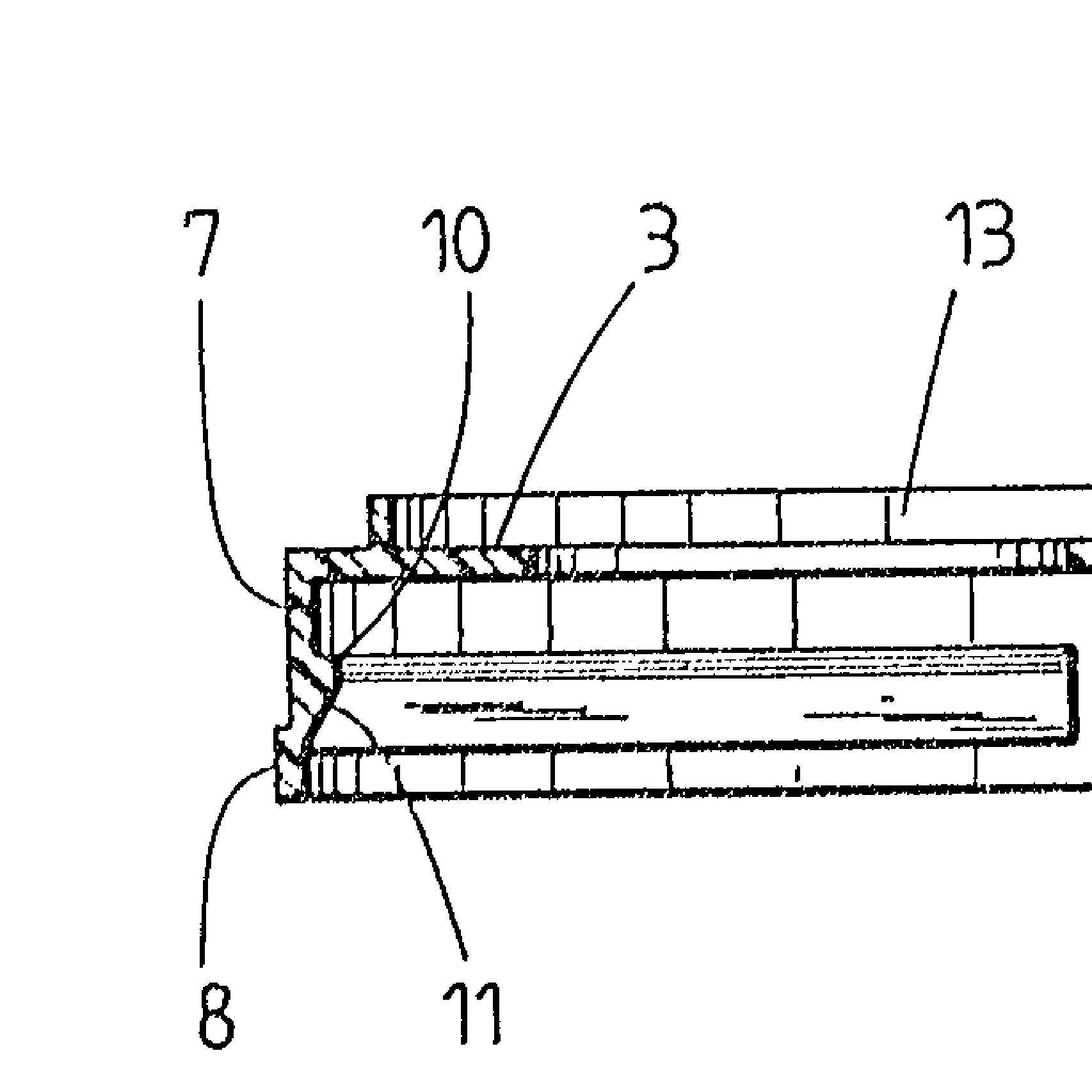
Peripheral side wall 4 has two sections 7,8 of diEEerent diameters
and di~ferent heights, whereby the first section 7 adjolning ring 3
of the upper end and constituting more than two th:irds of the height
of the wall has a diameter which, by cornparison with that of the
second section 8, is srrlall.
7 ~' 3 ~
--6--
1 ~he wall section adjoining ring 3 has, roughly in the middle of its
wall height, a peripheral projection 9 facing inward and provided in
each case with discontinuities coaxial with the centre lines, the
inner diameter of said projection being smaller than the diameter of
the first section, whereas its ~ide lO facing ring 3 is designed so as
to be plane and i9 arranged parallel to ring 3.
Ihe side of projection 9 facing away from ring 3 is designed as
bevel 11, which, at the edge Eorming the inner diameter of projection
9, drops off towards the end oE the end wall section 7 facing away
from ring 3 in such a manner that at this point the inner diameter of
first sectiorl 7 and the inner diameter of bevel 11 of projection 9
starting at this point are identical.
Second section 8 of side wall 4 has, by comparison with first
section 7, a larger diameter and starts at the side of projection 9
facing away from ring 3, respectively, while ending at a distance
from the latter.
Projection 9 is in every case provided with discontinuities coaxially
with the centre lines of device 1 or tie-bars 5, respectively, i.e.
it starts and ends in every case at a distance from centre lines 12
as shown in Figs. 2 and 1.
~he side of ring 3 of hold-down device 1 facing away from side wall 4
is provided with a rib-type second ring 13 as shown in Fig. 2, said
ring being arranged concentrically peripheral and at a distance from
the outer edge of horizontal ring 3, as shown in Fig. 1. Furthermore,
ring 13 is arranged vertically, i.e. at an angle of 90, in respect
of ring 3.
Horizontal ring 3 as well as tle-bars 5, centre 6, side wall 4 and
projection 9 are made in one plece.
I~old-down device 1 can be stacked together with others both before
and aEter use, whereby second section 8 of s:ide wall 4 at least partly
encompasses in every case Eir9t section 7 of side wall 4 of hold-dow~
device 1 imme~iately below, and annNlar surface 3 of the upper end
3 ~i
--7--
1 and the outer edge of the surface on the side of ring 13 facing away
from side wall 4 of lower hold-down device 1 engages the underside of
projection 9 or bevel 11 of projection 9 of hold-down device 1
immediately above, so that a plurality of devices can be stacked in
non-slip manner one above the other.
~uring application of the cap-type hold-down device 1, the latter i9
mounted on the upper end of a can and a conventional lid, as shown in
Fig. 3. To this end, projection 7 is so pressed over bead 15 at the
upper end of can 14 as initially to cause bevel 11 to slide along
bead 15 so that face 10 of projection 9 facing the upper end of hold-
down device 1 and designed in plane manner engages the underside of
bead 15 and hold-down device 1 is firmly seated on can 14. In this
state there i9 a small distance or only slight contact between the
underside of ring 3 and tie-bars 5 of hold-down device 1 and lid 16
which is to be secured, thu~ ensuring that projection 9 encompasses
head 15 also if the height of said bead is subject to any tolerances.
Owing to the s~ll distance or slight contact between the underside
of ring 3 and tie-bars 5 and the upper face of lid 16 and owing to
the firm seat of device 1, only a slight theoretical displacement of
lid 16 is possible, i.e. a displacement the effect of which is
insignificant, as a result of which said lid remains closed by means
of hold-down device 1 even ~ith inappropriate use of can 14, i.e. if
for instance can 14 falls from the platform of a truck.
Owing to the recesses or discontinuities provided in projection 9
along its peripheral extent, it is possible to introduce, with a vie~
to removing device 1 or hold-down device 1, a tool or auxiliary device
between bead 15 of can 14 and side wall 4 of hold-down device 1, 50
as to be able to detach hold-down device 1 Erom can 14 without the
use of Eorce oc any other problems.
If several cans are to be stoced, they can also be stacked one above
the other with the aid of hold-down dev:ice l, in wn:ich case ring 13
vertically arranged on hold-down device 1 engages the special or
conventional indentations 17 in the bottom of` the can (as shown in
Fig. 3) oE the can to be stacked immediately above, thus ensuring
non-slip storage or stacking, respectlvely, of cans.
2 ~ 7
--8--
1 Fig. 4 shows an embod~nent of the device according to the inven~ion,
~ith eigh~ tie-bars 5. Furthermore, lugs 18 are shown with this
~nbodiment, which, as can also be seen in Figs. 5 and 6 constituting
a croqs-section or pætial cross-section of Fig. 4, are arranged in
S such a way as to extend from the surface at the upper end inwæ d.
They may press against the edge of the lid mounted on the can and
press said edge of the lid against the inner edge of the can. Also
shown i5 a lug 18 which can press or be pressed against the centre of
the lid of the can. In all other respects reference i9 made to the
co~nents in respect of Fig. 1 with a view to explaining the embod~nent
~hown in Figs. 4, 5 and 6. The reference numbers used in regard to
side wall 4, projection 9 and ring 13 (stacklng bead) in Fig. 6 are
the same as the reference numbers in Fig. 2.
Fig. 6 shows ring 13 at a distance from the side wall, i.e. its outer
and inner diameters are smaller than the overall diameter of the
device. However, ring 13 can also be displaced towards the outer edge
so as to form an extension of side wall 4.