Note : Les descriptions sont présentées dans la langue officielle dans laquelle elles ont été soumises.
20Z8748
-- 1 --
CROSS-REYER~NCE
This application is related to my copending
application Serial No. 07/336,793 filed April 12, 1989,
as well as my already issued U.s. Patent No. 4,331,216.
05 BACKGROU~p OF TH~ INVENTION
Pield of the Invention
The present invention relates to new and use~ul
improvements to tree and pole climbing apparatu~ and,
more particularly, to apparatus comprising two climbing
members which are alternately raised by the user to
reach a desired elevation in a tree or similar
structure. Such structures are generally referred to in
the art as tree stands.
De~cription of the Prio~ Art
Hunters, wildlife photographers, and others
often seek to climb trees or other vertical members and
remain com~ortably perched at the desired elevat~on
until an animal emerges. To meet this need, a number of
tree and pole climbing ~tructures exist in the prior
art. Often, thesQ structures include a seat to
accommodate the user who may o~ten remain at the
elevation for several hours.
Exemplary patents relating to tree climbing
stands which include a seat are:
U.S. Patent No. 4,331,216 to Amacker;
U.S. Patent No. 4,475,627 to Eastridge;
U.S. Patent No. 4,589,522 to Shelton;
U.S. Patent No. 4,667,773 to Davis; and
! U.S. Patent No. 4,802,552 to Williams.
With each of the disclosed devices, however, the
distance between the seat and the platform cannot be
varied. Hence, users who are taller or shorter than
average are forced to sit uncomfortably crouched or with
their feet dangling.
An attempt to obviate the aforementioned
problem was described in U.S. Patent No. 4,458,782 to
: ` . ~ .: . , .
- 2 - 202~7~
Meyer. Meyer discloses a tree stand seat construction
having a rigid seat 35 which is removably mounted to the
diagonal frame members 21, 22. A plurality of holes are
provided in the frame to allow the seat position to be
05 upwardly or downwardly adjusted. However, a significant
disadvantage of this device is the fact that as the
helght of the seat relative to the platform is varied,
the distance between the seat and the tree is also
varied. Hence, adjustment to fit the height of the
individual user is quite limited.
In the Eastridge, Davis, Williams and Shelton
patents noted herein the seat is hingedly secured to the
platform by means of pin or bolt members. Each of the
pins or bolts extend through holes provided in the chair
legs which support the seat. In time, the pins buckle
or the ends of the legs break off, rendering the stand
unsafe or useless. Moreover, this seat arrangement does
not provide enough friction to allow the seat to be
positioned upright by itself without requiring the tree
for support.
It would therefore be desirable to provide a
tree climbing stand having a seat construction which can
be easily adjusted to suit the height of the user and
which has a safe, secure, strong, and e~fective means
for securing the seat to the platform.
SU~MA~Y ANQ OBJECTS OF TH~ INVENTION
In view of the foregoing, it should be apparent
that a need still exists in the art for a tree stand
that avoids the problems inherent in the prior art
structures and which will allow its user to sit
comfortably while perched in the tree.
Accordingly, it is a primary object of this
invention to provide a tree climbing stand which is
compact, rugged, safe, portable, and convenient to
operate in the field.
Another object of this invention is to provide
a tree climbing stand provided with a seat which may be
2~287~3
-- 3
easily adjusted to suit the height of the user.
Yet another object of this invention i5 to
provide a tree climbing stand of the aforesaid type
wherein the seat can be easily removed at the discretion
05 of the user.
A further object of the present invention is to
provide a tree climbing stand of the aforesaid type
having an improved means for securing the seat to the
stand.
These and other ob~ects and advantages that
will become apparent hereinafter are accomplished in
accordance with the invention by providing a tree
climbing stand comprising a lower climbing section. The
lower section includes gripping members to engage the
tree, a support platform, and a flexible seat
construction mounted on the platform by a pillow block,
or U-shaped clamp or a sleeve. The distance between the
seat and the platform may be varied by telescoping seat
legs. The telescoping legs may be locked in place at
the desired height using spring-biased locking pins. In
another aspect of the invention the seat construction
may be completely removed from the support plat~orm ~or
easy storage, transportation or replacement.
The upper section includes gripping means to
engage the tree and functions to support the user's arms
during climbing.
With the foregoing and other ob~ects,
advantages and features of the invention that will
become hereinafter apparent, the nature of the invention
may be more clearly understood by reference to the
following detailed description of the invention, the
appended claims and to the several views illustrated in
the attached drawings.
BRIEF DESCRIPTION OF THE DRAWINGS
Fig. 1 is a perspective view showing the tree
stand of the present invention in use.
20Z8~
-- 4 --
Fig. 2 is a front elevational view showing the
telescoping frame for the seat construction of Fig. 1.
Fig. 3(a) is a side view partially in section
of the spring-biased locking pin.
05 Fig. 3(b) is a view similar to Fig. 3(a)
showing an alternative embodiment of the pin.
Fig. 4(a) is a side elevational view of the
U-shaped clamp embodiment for supporting the seat frame
of Fig. 1.
Fiq. 4(b) is a front elevational view partly in
section of the sleeve embodiment for supporting the seat
frame of Fig. 1.
Fig. 4(c) is a side elevational view partly in
section of the sleeve embodiment taken along line 4(c)
of Fig. 4(b).
Fig. 5 is an elevational view of the serrated
gripping wedge.
Fig. 6 is a perspective view of the guard
employed with the serrated gripping wedge.
Fig. 7 is an elevational view of the serrated
gripping wedge with the guards attached.
DETAILe~L~E5~FIpTIQN-QF THE l .~ oDIM~N~
Referring now in detail to the drawings wherein
like parts are designated by like reference numerals
throughout, there is illustrated in Fig. 1 a preferred
embodiment of the tree climbing stand of the present
invention, designated generally by reference numeral 10,
in engagement with a tree T.
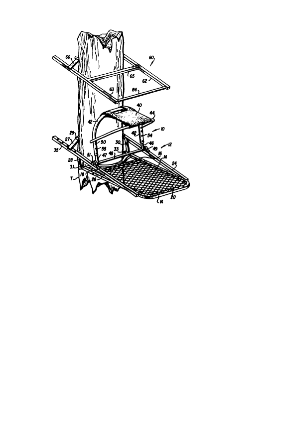
As seen in Fig~ 1, tree stand 10 includes a
lower, seating section or assembly 12 having a
generally U-shaped frame 14 preferably formed of
aluminum or steel hollow square tubing. A support bar
16 is transversely mounted to frame 14 adjacent the
tree. A curved bar 18, which engages the tree or
column, is secured at its ends to frame 14 and at its
center to support bar 16. An overlying steel mesh 20 is
;~028~
-- 5 --
secured to frame 14 and support bar 16 by welding or the
like to provide a platform on which a user may stand.
A pair of generally parallel spaced bars 24, 26
are hingedly mounted to opposite sides of frame 14
05 towards the front end of the frame 14 using conventional
pin or bolt construction (not shown). A conventional
V-shaped gripping wedge 27 is removably mounted at the
opposite ends of spaced bars 24, 26 ~or securing the
stand to the back side of the tree as shown in Fig. 1.
A plurality of cleats 29 may be welded to the wedge
member 27 to provide the needed penetration into the
side of the tree opposite the curved bar 18.
Alternatively, gripping wedge 70 provided with
serrations, or saw-teeth 72 may be employed (Fig. 5).
When weight is applied to the stand, the serrations 72
puncture the bark of tree T to provide additional
gripping support for the stand.
When the tree stand is not in use, guards 74,
preferably constructed of rubber or plastic may be
fitted over the serrations 72, as shown in Fig. 7. The
guards comprise an elongated strip having a generally
"U" shaped cross-section (Fig. 6). Guards 74 may be
formed in one piece, if desired. The guards are
particularly useful in those ~urisdictions where it is
prohibited by law to use tree stands which puncture the
bark o~ trees.
Conventional bolt and wing nuts may be used to
secure the wedge 27 or 70 to the spaced bars 24, 26 via
apertures 35 provided in bars 24, 26. This construction
allows the distance between curved bar 18 and gripping
wedge 27 to vary depending on the diameter of tree T.
A pair of struts 28, 30 are pivotably mounted
at one end to spaced bars 24, 26, respectively, and at
their opposite ends to a pair of telescoping bars 31,
33. The telescoping bars 31, 33 are positioned within
and in slidable engagement with each side of U-shaped
frame 14 which is hollow. The pivoting spaced bars 24,
26, struts 28, 30, and telescoping bars 31, 33 cooperate
- . ~ . . .
' ' ~' .',. : .
.
- 6 - 20287~8
to allow the lower assembly 12 to collapse to facilitate
ease in transport and storage.
Further details of the gripping cleats, which
may be fixed or removable, as well as the telescoping
05 bar arrangement are described in my copending
application Serial No. 07/336,793 and my already issued
U.S. Patent No. 4,331,216, the subject matter of which
i8 incorporated herein by reference.
The improved seat construction of the present
invention includes a seat 40, preferably constructed of
canvas, attached at its rearward end to a first tubular
U-shaped frame member 42 and at its forward end to a
second U-shaped frame member 44 which is pivotably
sécured to the first U-shaped member 42 at 45 using
conventional bolts (Fig. 2). In this manner seat frame
members 42 and 44 fold neatly within themselves for ease
in transport and storage with the flexible seat 40
positioned therebetween.
As best viewed in Fig. 2, the opposite legs of
tubular frame member 42 telescopingly receive vertical
tubes 46, 47, which pro~ect ~rom a transverse rod 48.
Rod 48, in turn, is rotatably secured at opposite ends
within pillow blocks 49, 51 mounted on parallel bars 24,
26, respectively.
A second method o~ mounting the transverse rod
48 may be accomplished by use of generally U-shaped
brackets 55, as shown in Pig. 4. Brackets 55 compri~e a
piece of steel or aluminum curved to accommodate and
retain the ends of horizontal member 49, which is less
expensive than pillow blocks 49, 51. The brackets 55
are easily mounted to bars 24,26 by bolts, welding, or
the like.
A third method of mounting the seat frame to
the platform side bars 24, 26 is illustrated in Figs.
4(b) and (c). Vertical tubular members 46, 47 are
welded to a tubular sleeve 82 which surrounds a
transverse rod or tube 80 and is rotatable about tube
80. In turn, transverse tube 80 is welded to the
.. .
:
- . . .
2028~D~8
logitudinally extending platform bars 24 and 26. Sleve
82 is preferably of a length substantially extending the
length of transverse tube 80 such that sleeve 82
generally abuts platform bars 24 and 26. If desired,
05 two short sleeves can be used, each of which is welded
to a respective vertical tube 46, 47. A similar
construction is shown in U.S. Patent No. 4,802,552 (Fig.
6). The arrangement of the present invention, however,
prevents the seat frame from shifting from Ride-to-side
thereby fixing the seat in the center of the stand where
the weight of the user is most evenly distributed.
Additionally, by using a one-piece sleeve 82, instead of
using the conventional two sleeve arrangement, earlier
noted, when the seat of the present invention is removed
the distance between vertical tubes 46, 47 is fixed.
As mentioned, one disadvantage of the prior art
is the fact that the hinge connection which secures the
seat legs to the platform requires bolts which penetrate
holes provided in the platform frame and the seat legs.
The inclusion of pillow blocks 49, 51, or clamps 55
obviate this disadvantage. Moreover, it will be
appreciated that the pillow blocks or clamps are
con~tructed to provide sufficient friction to allow the
seat frame to remain upright when it is not resting
against the tree and yet will permit rotation of the
seat with relative ease for folding purposes. Another
disadvantage of the prior art --that the height of the
seat cannot be varied-- is obviated by providing
telescoping frame members in the seat frame
construction, which allows the seat to be secured in
place at various elevations.
With reference to Fig. 3, locking means,
comprising a spring 56, is positioned at its downward
end to the inside surfaces of each of the vertical tubes
46, 47. In the embodiment of Fig. 3(a) spring 56 is
fixedly in position by suitable means, such as weldment
W. At the opposite end of the flat spring 56 is mounted
a pin 50. The pin is biased into engagement with
- , -. :: .
,
20287~8
aperture 52 provided in each of vertical tubes 46, 47
and one of a plurality of apertures 54, 55 provided in
each leg of the U-shaped frame member 42 when the
apertures in frame 42 becomes coincident with the
05 apertures of vertical tubes 46, 47, as shown in Fig. 3.
In the embodiment of Fig. 3(b), spring 56 is a
unitary push spring such as Valco (of Cleveland, Ohio)
No. 0183-250, which is a one-piece U-shaped member in
which the pin is integrally formed at one end of the
spring. The spring may thus be readily inserted and
removed from the vertical tubes 46,47.
To raise, lower, or remove the seat, the user
merely depresses pin 50 and slides frame member 42 to
the desired selected position represented by one of the
drilled apertures. The pin 50 automatically projects
the selected aperture and is locked in place.
In the illustrated embodiment, three apertures
54 and three apertures 55 are provided in each of the
two legs of frame member 42. The two pairs of three
apertures 54,55 are arranged in the legs of frame member
42 with a spacing of 2 inches, and are positioned so as
to provide an ad~ustment of seat 40 above platform 20 at
three levels of 20 inches, 24 inches, and 26 inche~,
respectively, so as to provide a maximum amount of
comfort for the stand user when the stand is in position
on tree T, with the seat in the upright, or erected
position.
To allow the seat 40 and frame members 42 and
44 to fold down flat for ease in transport and storage,
vertical tubular members 46, 47 are mounted to a
horizontal member 48 which is rotatably secured within
pillow or bearing blocks 49, 51.
An additional advantage provided by the afore-
mentioned structure lies in the fact that the seat 40,
together frame members 42 and 44 may be readily removed
from frame 14, allowing more flexibility in the use of
the stand.
~: -
'
2028~a~8
g
An upper frame 60 is provided for climbing anddescending the tree or pole. Upper frame 60 is
constructed of a pair of parallel side bars 52, 63
spaced by a pair of cross bars 64, 65 and a gripping
05 wedge 66. The manner of use of upper and lower frames
for climbing are described in my U.S. Patent No.
4,331,216, at columns 6 and 7, wh$ch is incorporated
herein by reference.
Although only preferred embodiments are
specifically illustrated and described herein, it will
be appreciated that many modifications and variations of
the present invention are possible in light of the above
teachings and within the perview of the appended claims
without departing from the spirit and intended scope of
the invention.
.... . . . ~
- .
.
,
.
- ......... . ..
.. . . ,: .
. .