Note : Les descriptions sont présentées dans la langue officielle dans laquelle elles ont été soumises.
2~2~3~
UNION JOINT
DESCRIPTION
The present invention relates to a union joint and,
more particularly, to a union joint for use in
semiconductor industries requiring perfectly sealed
connection of pipes.
Semiconductor device manufacturing processes for
manufactuing semciconductor devices, such as ICs and LSIs,
are carried out in clean rooms in which elaborate
precautions are employed to reduce dust particles and
other contaminants in the air. A special gas for use in
the clean room is supplied through piping from an external
gas source~ The special gas must be extreme]y pure and
the existence of foreign gasses, such as air, in the
special gas must be perfectly obviated~ Therefore, the
piping for supplying the special gas must be formed of
precision pipes and precision union joints for connecting
the pipes. Union joints to be used in combination with
high-pressure vessels also must be capable of perfect
sealing in view of safety.
The perfectly sealed connection of pipes by a
conventional union joint may be attained by increasing
pressure acting on a metallic gasket provided between the
pipes. However, if an excessive torque is applied to the
coupling ring to join pipes firmly, the pipes and a gasket
2~2~13~
, .
gasket interposed between the pipes are distorted
torsionally, and hence the torque cannot be increased
beyond a fixed limi-t.
The applicant of the present patent application
proposed previously a union joint as shown in Fig. 4
incorporating a thrust bearing to transmit only an axial
force from the inner surface of a coupling nut -to one of
two pipes and not to transmit torque from the inner
surface of the coupling nut to the pipe in 3apanese Patent
Laid-Open Publication No. 62-75188. As shown in Fig. 4,
the union joint consists of a first sleeve 10 attached in
a sealed joint to a first pipe 1, a second sleeve 20
attached in a sealed joint to a second pipe 2, a metallic
gasket 30 interposed between the pressing surface 15 of
the first sleeve 10 and the pressing surface 25 of the
second sleeve 20, a coupling nut 5 for axially drawing
together the first sleeve 10 and the second sleeve 20 to
join the first pipe 1 and the second pipe 2 hermetically,
and a thrust bearing 8 placed between the inner bottom
surface 6 of the coupling nut 5 and the shoulder of the
first sleeve 10. When the coupling nut 5 is turned to
draw together the first sleeve 10 and the second sleeve
20, hence the first pipe 1 and the second pipe 2, only an
axial force acts on the first sleeve 10, so that the pipes
1 and 2 can be firmly joined together by applying a large
torque to the coupling nut 5 without torsionally distoring
the pipes 1 and 2 and the metallic gasket 30. In order to
21~2~3~
enhance the sealing effec-t of the union joint, the
pressing surface 15 of the first sleeve 10 and the
pressing surface 25 of the second sleeve 20 are mirror-
finished and, to enhance the possibility of repetitive
use, the pressing surfaces 15 and 25 are burnished. The
metallic gasket 30 having excellent squeezing property,
capable of securing residua] elasticity, capable of
functioning without contaminating the gas and having
exce]lent durability can be used repeatedly to meet
economical requirements.
To reserve an appropriate residual elasticity of the
metallic gasket 30, the compression of the metallic gasket
30 between the sleeves 10 and 20 must be within a limited
range. To limit the compression of the metallic gasket
30, the sleeves 10 and 20 are provided respectively with
limiting surfaces 16 and 26. To locate the metallic
gasket 30 correctly between the sleeves 10 and 20, a
gasket chamber S surrounded by a side wall 28 is formed in
the second sleeve 20. In a sate shown in Fig. 4 before
the coupling nut 5 is turned to fasten together the
sleeves 10 and 20, the metallic gasket 30 is placed in the
gasket chamber S and seated on the pressing surface 25
formed in the second sleeve 20, and the pressing surface
15 of the first piece is positioned opposite to the
metallic gasket 30 in the gasket chamber S. When the
coupling nut 5 is turned to draw the sleeves 10 and 20
axially toward each other, the metallic gasket 30 is
2~3~
compressed be~ween the pressing surfaces 15 and 25 until
the lmiting surfaces 16 and 26 are brought into contact
with each other.
This union joint, however, still needs further
improvements. Since the pressing surface 15 of the first
sleeve 10 is the end surface of a protruding portion of
the first sleeve 10, the pressing surface 15 can be
quickly and easily burnished. However, since the pressing
surface 25 of the second sleeve 20 is the bottom surface
of the recessed gasket chamber S, it is considerably
difficult to burnish the pressing surface 25 and
burnishing the pressing surface 25 increases the cost of
the union joint. Since the metallic gasket 30 expands
radially when compressed and the outer circumference of
the metallic gasket 30 approaches the side surface 28 of
the gasket chamber S, the entire area of the pressing
surface 25 including the peripheral area contiguous with
the side surface 28 must be burnished, which, however, is
very difficult. Means for locating the metallic gasket 30
in a gasket holding space S' on the circumference 28' of
the protruding end of the second sleeve 20 as shown in
Fig. 7 also has the same problem in burnishing the
pressing surface 25 on which the metallic gasket 30 is
seated.
The union joint has problems in assembling and
disassembling. In axially separating the sleeves 10 and
20 in a space where the pipes 1 and 2 cannot be axially
.. . . . . . .
.
2~293~
.. ~ .
moved after screwing the coupling nut 5 off the second
sleeve 20, the pressing surfaces 15 and 25 need to be
moved laterally with respect to an axis P, which, however,
is impossible because part oE the protruding end 18 of the
first sleeve 10 is fitted in the gasket chamber S.
In some cases, minute radial flaws 50 as shown in
Figs. 5 and 6 are formed across a portion of the pressing
surfaces 15 (25) to be in contact with the metallic gasket
30. Such a radial flaw 50 makes impossible to secure
perfect sealing however great is the pressure applied to
the metallic gasket 30, because the metallic gasket 30
does not cut into the radial flaw 50 and expands radially
after the pressure applied to the metallic gasket 30
exceeds a certai level.
Accordingly, it is an object of the present invention
to provide a union joint having pressing surfaces which
can be readily burnished/ and capable of being easily
assembled, of being manufactured at a relatively low cost
and of securing perfect sealed connection of pipes.
In one aspect of the present invention, a union joint
comprises a first sleeve, a second sleeve, a metallic
gasket interposed between the first and second sleeves so
as to be compressed between the respective pressing
surfaces of the first and second sleeves when the first
and the second sleeves are drawn axially toward each
other, a coupling nut for drawing the first and second
.,
--` 2 01293~
sleeves axially toward each o-ther, and is characterized in
that grooves having a shape substantially conforming to
the external shape of the metallic gasket are formed
respectively in the respective pressing surfaces of the
first and second sleeves, a retaining member for retaining
the metallic gasket in place i5 detachably put on either
the first or second sleeve, the metal]ic gasket has a
cross section resembling the letter C, the retaining
flange of the retaining member is inserted in the slit of
the metallic gasket to retain the metallic gasket in place
on the corresponding sleeve, and the retaining member has
a limiting portion which engages the end surfaces of the
first and second sleeves to limit the compression of the
metallic gasket.
The metalllc gasket can be retained securely on the
sleeve by inserting the retaining flange of the retaining
member in the slit of the metallic gasket and putting the
retaining member on the sleeve, which facilitates work for
assembling the union joint regardless of the position of
the same. The metallic gasket expands radially and is
brought into contact with the bottom surfaces of the
grooves of the sleeves in wide areas when compressed by
screwing the coupling nut on the sleeve so that the
possibility of inclusion of radial flaws formed in the
bottom surfaces of the grooves in the sealed contact areas
is increased. The end surfaces of the sleeves come into
contact with each other to limit the compression of the
,
.
~ 2~3~
metallic gasket when the first and second sleeves are
drawn axially toward each otherl so -that the metallic
gasket is eompressed properly.
The union joint can be readily disassembled by
screwing the coupling nut off the sleeve, and the metallie
gasket ean be rea-lily and quickly ehanged by laterally
dislocating the sleeves relative to each other.
The above and other objects, features and advantages
of the present invention will become more apparent from
the following description taken in connection with the
accompanying drawings.
Fig. 1 is a longitudinal sectional view of a union
joint in a preferred embodiment according to the present
invention;
Fig. 2 is a cross sectional view of a modification of
a retaining member;
Figs. 3(A) and 3(B) are typieal views of assistanee
in explaining the funetion and effeet of a groove for
reeeiving a metallie gasket;
Fig. 4 is a longitudinal seetional view of a
eonventional union joint;
Figs. 5 and 6 are views of assistance in explaining
the adverse effect of flaws formed in the pressing surface
of a union joint on the sealing effect of a metallic
gasket; and
Fig. 7 is a fragmentary sectional view of a
2~2~3~
conventional ~nion joint, showing another manner of
holding a metallic gasket on a sleeveO
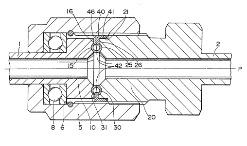
Referring to Figs. 1 to 3, a union joint embodying
the present invention comprises a first sleeve 10
hermetically joined to a first pipe 1, a second sleeve 20
hermetically joine-l to a second pipe 2, a co~pling nut 5
combine-l with the first sleeve 10 so as to be screwed on
the second sleeve 20 to draw the first sleeve 10 and the
second sleeve 20 axially toward each other, a thrust
bearing 8 placed between the inner flange of the coupling
nut 5 and the shoulder of the first sleeve 10 to allow the
coupling nut 5 to be turned without dragging the first
sleeve 10, a metallic gasket 30 placed between the first
sleeve 10 and the second sleeve 20, and a retaining member
40 having a retaining flange 42 inserted in the slit of
the metallic gasket 30 and put on the reduced front end of
the second sleeve 20 to retain the metallic gasket 30 in
place on the second sleeve 20 and to limit the compression
of the metallic gasket 30 when the first sLeeve 10 and the
second sleeve 20 are drawn axially toward each other.
Grooves 15 and 25 corresponding to pressing surfaces
and conforming to the external shape o~ the metallic
gasket 30 are formed respectively in the respective end
surfaces 16 and 26 of the first sleeve 10 and the second
sleeve 20 to receive the metallic gasket 30 therein.
Since the grooves 15 and 25 are exposed the bottom
. . .~ .
.
~ 2~9~
surfaces of the grooves 15 and 25 can be easily burnished
at a low cost.
When compressed, the metallic gasket 30 is pressed
firmly to the bottom surfaces of the grooves 15 and 25 as
shown in Fig. 3(A), and then the metallic gasket 30 is
expanded radially as shown in Fig. 3~B) as the compressive
pressure acting on the metallic gasket 30 increases,
whereby the effective sealing area, namely, a contact area
between the metallic gasket 30 and the grooves 15 and 25,
is increased to increase the possibility of inclusion of
flaws, if any, formed in the circumference of the metallic
gasket 30 and the bottom surfaces of the grooves 15 and
25. The cross section of the grooves 15 and 25 may be of
a semicircular shape or a shape resembling the letter V
provided that the side surfaces of the metallic gasket 30
are able to come into close contact with the corresponding
bottom surfaces of the grooves 15 and 25 when the metallic
gasket 30 is compressed.
The bottom surfaces of the grooves 15 and 25 formed
respectively in the end surfaces 16 and 26 of the sleeves
10 and 20 can be easily burnished.
The retaining member 40 is put on the reduced end 21
of the second sleeve 20, and the retaining flange 42 is
inserted in the slit of the metallic gasket 30 to retain
the metallic gasket 30 in place in the groove 25 of the
second sleeve 20. A compression limiting portion 46 is
formed in the retaining flange 42 of the retaining member
~293~4
40. When the sleeves 10 and 20 are drawn axially toward
each other by the coupling nut 5, the compression limitng
portion 46 is held between the respective end surfaces 16
and 26 of the sleeve 10 and 20 to limit the Eurther
co~npression of the metallic gasket 30. Thus, the
compression of the metallic gasket 30 is dependent on the
thickness of the compression limiting portion 46 of the
retaining member 40. The retaining member 40 may be
replaced with other retaining member of dimensions
different from the former to adjust t.he compression of the
metallic gasket 30.
Although the invention has been been described in its
preferred form with a certian degree of particularlity,
obviously many changes and variations are possible
therein. It is therefore to be understood that the
present invention may be practiced otherwise than as
specifically described herein without departing from the
scope and spirit thereof.
' , ' .
'' ' ~
.