Sélection de la langue

Search

Sommaire du brevet 2029978 

Énoncé de désistement de responsabilité concernant l'information provenant de tiers

Une partie des informations de ce site Web a été fournie par des sources externes. Le gouvernement du Canada n'assume aucune responsabilité concernant la précision, l'actualité ou la fiabilité des informations fournies par les sources externes. Les utilisateurs qui désirent employer cette information devraient consulter directement la source des informations. Le contenu fourni par les sources externes n'est pas assujetti aux exigences sur les langues officielles, la protection des renseignements personnels et l'accessibilité.

Disponibilité de l'Abrégé et des Revendications

L'apparition de différences dans le texte et l'image des Revendications et de l'Abrégé dépend du moment auquel le document est publié. Les textes des Revendications et de l'Abrégé sont affichés :

  • lorsque la demande peut être examinée par le public;
  • lorsque le brevet est émis (délivrance).
(12) Demande de brevet: (11) CA 2029978
(54) Titre français: RACCORD POUR TUBES
(54) Titre anglais: TUBE CONNECTION
Statut: Morte
Données bibliographiques
(52) Classification canadienne des brevets (CCB):
  • 285/60
(51) Classification internationale des brevets (CIB):
  • F16L 23/00 (2006.01)
  • F16L 19/02 (2006.01)
  • F16L 19/028 (2006.01)
(72) Inventeurs :
  • GOFF, ROBERT W. J. (Royaume-Uni)
  • MUFFKE, WALTER (Allemagne)
(73) Titulaires :
  • BUNDY GMBH (Allemagne)
(71) Demandeurs :
(74) Agent: FETHERSTONHAUGH & CO.
(74) Co-agent:
(45) Délivré:
(22) Date de dépôt: 1990-11-14
(41) Mise à la disponibilité du public: 1991-05-16
Licence disponible: S.O.
(25) Langue des documents déposés: Anglais

Traité de coopération en matière de brevets (PCT): Non

(30) Données de priorité de la demande:
Numéro de la demande Pays / territoire Date
P 39 37 888.8 Allemagne 1989-11-15

Abrégés

Abrégé anglais


ABSTRACT

In a tube connection for thin-walled, small-
calibre metal tubes, in particular for braking, fuel
and hydraulic lines on motor vehicles, or for
refrigeration apparatus, at least one of the metal
tubes (1, 2) is provided on the end to be connected
with a flange (11, 12) and the metal tubes (1, 2) are
enveloped by a sleeve (3, 4; 7) in each case, of which
at least one sleeve (7) can be deformed by the effect
of a contact pressure on the sleeves (3, 4; 7) and thus
on the flanges (11, 12) so as to form a connection
between the sleeves (3, 4; 7), at least one of the
sleeves (3, 4) consists of a part 4, which can be
connected to the other sleeve (7) by deformation, and a
part (3) which envelopes the metal tube (1) and which
enables a releasable connection to be provided between
the parts (3, 4).

Revendications

Note : Les revendications sont présentées dans la langue officielle dans laquelle elles ont été soumises.


8.
CLAIMS

1. Tube connection for thin-walled, small calibre
metal tubes, at least one of the metal tubes being
provided on the end to be connected with a flange and
the metal tubes being enveloped by a sleeve in each
case, of which at least one can be deformed by the
effect of a contact pressure on the sleeves and thus on
the flange so as to form a connection between the
sleeves, characterised in that at least one of the
sleeves (3, 4; 21, 22; 25, 28) consists of a part (4,
22, 28) which can be connected to the other sleeve (7,
29) by deformation and a part (3, 21, 25) which
envelopes the metal tube (1) and in that a releasable
connection (5, 6) is provided between the parts.
2. Tube connection according to claim 1,
characterised in that the releasable connection
comprises a screw connection (5, 6).
3. Tube connection according to claim 1,
characterised in that both metal tubes are in each case
provided with a flange ( 11, 12).
4. Tube connection according to claim 1,
characterised in that one of the tubes is formed from
one of the sleeves or from a part of one of the sleeves
(Figure 5, 7).
5. Tube connection according to claim 2,
characterised in that in a manner known in itself a
first sleeve (3, 4; 21, 22; 25, 28) is provided with a
larger inside diameter in an area jutting out over the
end of the first metal tube (1) enveloped by the first
sleeve (3, 4; 21, 22; 25, 28), this inside diameter
being suitable for receiving a second sleeve
constructed as a partially thin-walled press bush (7,
29), in that an annular channel (10) which extends
around the inner wall of the first sleeve (3, 4; 21,

9.
22; 25, 28) is opposite the thin-walled part (8) of the
press bush (7, 29), in that the thin-walled part (8) of
the press bush (7, 29) can be sufficiently deformed
into the annular channel (10) by means of the contact
pressure and in that the first sleeve consists of two
parts (3, 4; 21, 22; 25, 28) which are connected by a
screw connection.
6. Tube connection according to claim 5,
characterised in that the screw connection (5, 6) in
the area of the larger inside diameter of the sleeve
(3, 4) is provided in such a way that both parts (3, 4)
of the sleeve have in each case a surface which is
accessible from the outside.
7. Tube connection according to claim 6,
characterised in that the parts (3, 4) of the first
sleeve have on the outside a hexagonal configuration.
8. Tube connection according to claim 5,
characterised in that a first part (21, 25) of the
first sleeve which envelops the first metal tube (1) is
provided at the periphery with an external thread, in
that a second part (22, 28) of the first sleeve
essentially envelops the first part (21, 25) and is
provided with an internal thread and in that the first
part contains recesses (23, 24) for inserting a key on
the end face remote from the flange of the first metal
tube (1).
9. Tube connection according to claim 8,
characterised in that the first part (25) is provided
with a circumferential flange (26) which is adapted to
be received in a circumferential recess (27) in the
second part (28).
10. Tube connection according to claim 5,
characterised in that the press bush (7, 29) is
provided with a flange at the end (9) projecting from
the first sleeve (3, 4; 21, 22; 25, 28).

10.

11. Tube connection according to claim 3,
characterised in that a connection tube (31) of a unit
is provided with an external thread which engages in an
internal thread of a first sleeve (33) which juts out
over the connection tube (31) and which has an inside
diameter t for receiving a second sleeve which is
constructed as a partially thin-walled press bush (29),
in that an annular channel which extends around the
internal wall of the first sleeve (33) is opposite the
thin-walled part of the press bush (29) and in that the
thin-walled part of the press bush (29) can be deformed
into the annular channel by means of the contact
pressure.
12. Tube connection according to claim 4,
characterised in that in a manner known in itself a
first sleeve (3, 4) has a larger inside diameter in an
area jutting out over the end of the first metal tube
(1) enveloped by the first sleeve (3, 4), this inside
diameter being suitable for receiving a second sleeve
constructed as a partially thin-walled press bush, in
that an annular channel which extends around the
internal wall of the first sleeve (3, 4) is opposite
the thin-walled part of the press bush, in that the
thin-walled part of the press bush can be deformed into
the annular channel by means of the contact pressure,
in that the first sleeve (3, 4) consists of two parts
(3, 4) which are connected by a screw connection and in
that the second sleeve forms a connection tube of a
unit.
13. Tube connection according to claim 12,
characterised in that the second sleeve is provided
with a flange (41) which forms a set surface for a
pressing tool.
Description

Note : Les descriptions sont présentées dans la langue officielle dans laquelle elles ont été soumises.


r~J j 7

~e ~onnetlo~

This invention relates to a tube connection for
thin~walled, small-calibre metal tubes, in particular
for braking, fuel and hydraulic lines on motor vehicles
S so that at least one of the metal tubes is provided on
the end to be connected with a flange and the metal
tubes are enveloped by a sleeve in each case 7 of which
at least one can be deformed by the effect of a contact
pressure on the sleeves and thus on the f]anges so as
to form a sealed connection between the sleeves.
Tube connections are used in the construction of
motor vehicles in positions which are difficult to
reach and must be formed in these positions with
special tools. The high fluid pressures in the lines
require appropriate sealing seats and sufficiently
large contact pressures on the sealing seats. In order
to facilitate the production of the tube connections,
because of the difficulty of reaching their locations,
tube connections are known on which permanent
deformation is used instead of a screw connection. A
non-destructive uncoupling is not possible however on
these tube connections.
The object of the invention is to propose a tube
connection which can be fitted in a simple manner and
which can be separated where necessary in a non~
destructive manner.
The tube connection according to the invention is
characterised in that at least one of the sleeves
consists of a part which can be connected to the other
sleeve by deformation and a part which envelops the
metal tube and in that a releasable connection is
provided between the parts. In this arrangement the
releasable connection consists preferably of a screw
connection. Two tubes can be provided in each case


with a flange or the connection can be formed between a
tube provided with a flange and a fixed connection tube
of a unit.
The tube connection according to the invention can
also be fitted with a simple tool in positions which
are difficult to reach. Moreover the invention also
permits the use of assembly robots and the two parts
can be joined together before they are brought to the
assembly area preferably by mechanical means directly
after the production of the two parts.
A tube connection known from German patent
specification DE 37 01 555 C1 enables assembly to be
carried out in a simple manner in that two sleeves
which envelop the flanged tube ends are pressed into
each other. A further development of the invention
combines the advantages of the known tube connection
with those of the tube connection according to the
invention in that in a manner known in itself a first
sleeve is provided with a larger inside diameter in an
area jutting out over the end of the first metal tube
enveloped by the first sleeve, this inside diameter
being suitable for receiving a second sleeve
constructed as a partially thin~walled press bush, in
that an annular channel which extends around the inner
wall of the first sleeve is opposite the thin-walled
part of the press bush, in that the thin-walled part of
the press bush can be sufficiently deformed into the
annular channel by means of the contact pressure and in
that the first sleeve consists of two parts which are
connected by a screw connection.
An advantageous embodiment of this further
development consists of the fact that the screw
connection in the area of the larger inside diameter of
the sleeve is provided in such a way that both parts of
the sleeve have in each case a surface which is

~L~i~J;~


accessible from the outside. ~ith this arrangement it
is particular]y advantageous that the parts of the
first sleeve have on the outside a hexagonal
configuration. This embodiment has the advantage that
spanners can easily be used for separating the tube
connection.
In accordance with another advantageous embodiment
it is arranged that a first part of the first sleeve
which envelops the first metal tube is provided at the
periphery with an external thread, that a second part
of the first sleeve essentially envelops the first part
and is provided with an internal 'chread and that the
first part contains recesses for inserting a key on the
end face remote from the flange of the first metal
tube.
According to the circumstances, this embodiment
results in particular in a shorter overall length of
the tube connection and although a special key is
required for separating the parts, this is advantageous
under certain circumstances as the connection according
to the invention is frequently used in systems where
safety is critical such as the braking system of a
motor vehicle. In addition with this arrangement the
first part can be provided with a circumferential
flange which is adapted to a circumferential recess in
the second part. In this way a stop is created when
the first part is screwed into the second part, which
is advantageous with the production by mechanical means
of the parts of the tube connection.
Another further development of the invention
consists of the fact that the press bush is provided
with a flange at the end projecting from the first
sleeve. In this way a greater application surface is
created for the tool used for assembly.
Exemplary embodiments of the invention are

illustrated in the accompanying drawings and are
explained in greater detail in the following
description, in which:
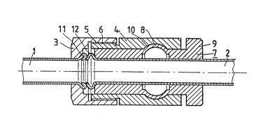
Figure 1 shows a longitudinal section through a
first embodiment;
Figure 2 shows a longitudinal section of a second
embodiment;
Figure 3 is a perspective view of the second
embodiment of Figure 2;
Figure 4 shows a longitudinal section through a
third embodiment; and
Figures 5 - 7 show embodiments in which a tube is
connected to a connection tube of a unit.
The same parts are shown in the various figures
with ~he same reference numbers.
The tube connection shown in Figure I is used for
connecting a first metal tube 1 having a conical flange
1I to a second metal tube 2 having a conical flange 12.
The metal tube 1 is provided with a sleeve consisting
of two parts 3 and 4, which in each case are provided
; with a thread 5 and 6. The external surfaces of the
parts 3 and 4 are formed with a hexagonal configuration
; so that they can accept in each case a spanner.
A partially thin-walled sleeve in ~he form of a
press bush 7 which envelops the metal tube 2 is
normally provided with a deformation zone 8, which
extends in a straight line in the unfitted condition.
The end 9 of the press bush 7 which is remote from the
flange 12 is constructed in the form of a flange.
The two-part sleeve envelops the metal tube 1
before assembly whilst the press bush 7 is applied to
the metal tube 2. Parts 3 and 4 of the sleeve are
preferably already put together in the works
immediately after they have been produced. To assemble
the connection the sleeve is slid over the press bush 7
until the flanges 11 and 12 are brought up forcefully

~ 2, ~ iq~

5.

against each other. The sleeve and the press bush 7
are pressed together axially with a suitable tool so
that the deformation zone 8 is deformed in the manner
shown and extends into a circumferential annular
channel 10 of the sleeve.
To release the connection, parts 3 and 4 of the
sleeve are turned against each other, so that the screw
connection is released. The parts can thus be released
and put together again in a simple manner.
The embodiment shown in Figure 2 is similar to
that of Figure 1 except that the screw connection is
formed differently between the parts 21 and 22 of the
sleeve so that the parts are simpler from a design
point of view. As the second part 22 extends over the
complete length of the sleeve the first part 21 cannot
be handled with a spanner. It is therefore provided
with corresponding recesses on the end face remote from
the flange 11 which in this case consist of two bores
23 and 24, into which a special key 30 can be inserted.
The press bush 29 is somewhat shorter in the second
embodiment than on the first embodiment.
Figure 3 shows a perspective view of the second
embodiment with indicated tools 30 and 31 for the
purpose of releasing and putting together again the two
parts 21 and 22 of the sleeve.
In the embodiment shown in Figure 4 the first part
25 of the sleeve is provided with a flange 26 which
engages with a circumferential recess 27 of the second
part 28. In this way an improved stop for the
pre-assembly of the parts 25 and 28 is achieved and, as
in the case of the second embodiment, bores 23 and 24
are provided for a special key 30 (Figure 2).
In the embodiment according to Figure 5 a
connection tube 31 of a unit 32, which is not shown in
great detail, and having an external thread, forms a


first part of a sleeve. The unit 32 may, for example,
consist of a brake cylinder or another assembly of a
hydraulic system. In ttliS arrangement the connection
tube 31 can be connected as a single part of the wall
of the unit 32 or can be connected to the wall by means
of a suitable thread. The end face of the connection
tube 31 is of conically-shaped construction so that it
is adapted to mate with the flange 12 of the metal tube
2.
In a similar manner to the arrangement of the
embodiment of Figure 2 a second part 33 of the sleeve
is provided with an internal thread and with a
circumferential annular channel 10. The press bush 29
corresponds substantially to that of the embodiments
according to Figures 2 and 4. If the unit is
incorporated in a motor vehicle with a second part 33
of the sleeve already screwed on to the first part 31,
all that is required is for the second metal tube 2 to
be introduced with the press bush 29 and for a
corresponding contact pressure to be exercised on the
press bush 29.
The embodiment according to Figure 6 is in itself
similar to that of Figure 1. Provision is simply made
for the fact that the second metal tube 34 represents a
connection tube of a unit of which only a part 35 is
shown. In order that a pressing tool can be used
without further manipulation when the press bush 7,
which is freely located on the metal tube 34, lies
against the wall 35 of the unit, the press bush 7 is
provided with an extension 36 which protrudes beyond a
radially extending flange 37, there-by enabling a
pressing tool to act on the flange 37.
In the embodiment of Figure 7 the press bush 39
forms the connection tube of a unit of which only a
part 35 is shown. For this purpose the press bush 39


7.

is adapted at its end face to mate with the flange 40
of the first rnetal tube 1. When the metal tube 1 is
assembled to the unit 35, a contact pressure could be
applied between the sleeve 3 and the unit itself. If
this should not be permissible or poss.ible the press
bush 39 may be provided with a radially extending
flange 41 which enables the contact pressure to be
applied between the sleeve 3 and the flange 41.
Although being especially applicable to tube
connections for braking, fuel and hydraulic lines on
motor vehicles, the tube connection of the present
invention has much wider application, and may also be
: used~ for example, in refrigeration apparatus.

Dessin représentatif
Une figure unique qui représente un dessin illustrant l'invention.
États administratifs

Pour une meilleure compréhension de l'état de la demande ou brevet qui figure sur cette page, la rubrique Mise en garde , et les descriptions de Brevet , États administratifs , Taxes périodiques et Historique des paiements devraient être consultées.

États administratifs

Titre Date
Date de délivrance prévu Non disponible
(22) Dépôt 1990-11-14
(41) Mise à la disponibilité du public 1991-05-16
Demande morte 1997-11-14

Historique d'abandonnement

Date d'abandonnement Raison Reinstatement Date
1996-11-14 Taxe périodique sur la demande impayée

Historique des paiements

Type de taxes Anniversaire Échéance Montant payé Date payée
Le dépôt d'une demande de brevet 0,00 $ 1990-11-14
Enregistrement de documents 0,00 $ 1991-12-04
Taxe de maintien en état - Demande - nouvelle loi 2 1992-11-16 100,00 $ 1992-10-08
Taxe de maintien en état - Demande - nouvelle loi 3 1993-11-15 100,00 $ 1993-10-14
Taxe de maintien en état - Demande - nouvelle loi 4 1994-11-14 100,00 $ 1994-08-07
Taxe de maintien en état - Demande - nouvelle loi 5 1995-11-14 150,00 $ 1995-10-13
Titulaires au dossier

Les titulaires actuels et antérieures au dossier sont affichés en ordre alphabétique.

Titulaires actuels au dossier
BUNDY GMBH
Titulaires antérieures au dossier
GOFF, ROBERT W. J.
MUFFKE, WALTER
Les propriétaires antérieurs qui ne figurent pas dans la liste des « Propriétaires au dossier » apparaîtront dans d'autres documents au dossier.
Documents

Pour visionner les fichiers sélectionnés, entrer le code reCAPTCHA :


Pour visualiser une image, cliquer sur un lien dans la colonne description du document. Pour télécharger l'image (les images), cliquer l'une ou plusieurs cases à cocher dans la première colonne et ensuite cliquer sur le bouton "Télécharger sélection en format PDF (archive Zip)" ou le bouton "Télécharger sélection (en un fichier PDF fusionné)".

Liste des documents de brevet publiés et non publiés sur la BDBC .

Si vous avez des difficultés à accéder au contenu, veuillez communiquer avec le Centre de services à la clientèle au 1-866-997-1936, ou envoyer un courriel au Centre de service à la clientèle de l'OPIC.


Description du
Document 
Date
(yyyy-mm-dd) 
Nombre de pages   Taille de l'image (Ko) 
Description 1991-05-16 7 277
Dessins représentatifs 1999-08-13 1 12
Dessins 1991-05-16 2 84
Revendications 1991-05-16 3 122
Abrégé 1991-05-16 1 21
Page couverture 1991-05-16 1 16
Taxes 1995-10-13 1 40
Taxes 1994-07-07 1 55
Taxes 1993-10-14 1 43
Taxes 1992-10-08 1 36