Note : Les descriptions sont présentées dans la langue officielle dans laquelle elles ont été soumises.
LASER-ABLATING A MARKING IN A
COATING ON PLASTIC ARTICLES
Field of the Invention
This invention relates to a process useful
5 in marking plastic articles, such as thin plastic
slides, with a bar code.
Background of the Invention
It is customary to provide bar codes on
dried, slide-like test elements used in analyzers to
test for analytes of liquids. The bar-code
information provides machine-readable information
such as the type of assay for that element, and
optionally, calibration data needed to calibrate that
particular test element.
1~ The test element body is typically a plastic
material, such as polystyrene. This underlying
material is not an easy material to print on. Thus,
conventional printing techniques have been difficult
to use as they do not always provide a sufficiently
contrasting color. A preferred format is to use a
white test element, hereinafter "slide~, with a dark
or black ink. Although flexographic printing of a
black ink has been used, this process suffers the
disadvantages of high cost, the need to print in
continuous web format and possible voids in the
printing.
Therefore, there has been a need prior to
this invention to develop a method of marking the
plastic slides by a technique other than printing.
Laser marking has been developed for
articles in general, as described, for example, in
U.S. Patent Nos. 4,323,755 and 4,515,867. However,
there is a problem in applying this technique to
plastic articles in general, and particularly to
polystyrene articles. That is, the coating that is
to be ablated away to reveal the contrasting color of
-2~ ?,~
the native plastic underneath, i8 not readily
ablatable without damaging the plastic with the
laser. That is, the contrasting color coating
adheres 80 well to the plastic that the last
molecules of the color do not readily ablate without
unduly damaging the plastic. This i8 particularly a
problem with certain plastic articles, euch as
polystyrene slides, that contain the dried reagents
used to assay for liquid analytes. That is, these
plastic articles, if ablated so as to remove some of
the plastic, will tend to flow so as to become warped
or distorted.
It is not entirely clear what the mechanism
is for the tenacious binding of the contrast color
coating to the plastic. It may be solvent attack of
the plastic, inherent porosity of the plastic
surface, or even a binding that is enhanced by the
heat of the ablation process. It appears to occur
whether or not the contrast color coating is
solvent-based or aqueous-based.
. Thus, prior to this invention the need for a
non-printing marking technique for use on plastic
articles was not met by laser-ablation technigues.
An additional problem arising from marking
by laser ablation is the tendency of the laser
process to cause redepositing of the contrast coating
in other areas. For this reason, laser marking of
lot numbers on bottles has in the past used large
dark areas and an ablation in the middle of that
area, so that the ablation debris falls onto the
bordering dark area, rather than a white area. The
disadvantage of this approach is that considerable
area is wasted in the large dark area that is
required.
Thus, a further problem has been to mark any
substance with laser ablation, without leaving debris
-3-
behind in white areas and without requiring large
areas of dark borders.
Summary of the Invention
- We have discovered a method of laser-marking
thin plastic articles that avoids the above-detailed
problems.
More specifically, in accord with one aspect
of the invention there is provided a method of
preventing damage to a pigmented plastic article when
ink on the article is ablated away to form an image.
The method comprises the steps of:
a) coating the plastic article with a
first layer of binder and solvent with a sufficient
wet-laydown to provide a dried coating coverage of at
least about 1.5 g/m ,
b) drying the first layer,
c) coating the first layer and plastic
with a colored coating comprising a binder and a
contrast color opposite to that of the pigment of the
plastic article, with a wet-laydown sufficient to
give a dried thickness sufficient to produce a
minimum print contrast of at least 0.75 compared to
the color of the plastic article,
d) drying the colored coating, and
e) in predetermined portions that form an
image, ablating away all of the colored coating and
at least some of the first layer, using a laser.
In accord with a second aspect of the
invention, there is provided a method of preventing
redepositing onto a support, material of a dark
coating that is laser-ablated from the support, the
method comprising the steps of ablating away a dark
coating on the support in areas needed for
information recording, and ablating away additional
portions of the coating beyond said areas of
information recording so that the additional portions
are free of redeposited material.
- ~J ~ U ~ ~
-4-
Accordingly, is it an advantageous feature
of the invention that markings such as bar-code
labeling can easily be placed on plastic articles
using a laser.
It is a related advantageous feature of the
invention that laser ablation can be used in such a
process without distorting the plastic article.
It is a further advantageous feature that
such ablation can be done without requiring a large
dark border around the information area.
Other advantageous features will become
apparent upon reference to the following Description
of the Preferred Embodiments, when read in light of
the attached drawings.
Brief Description of the Drawings
Fig. 1 is an enlarged elevational view in
section of a plastic article marked with a laser in
accordance with one aspect of the invention;
Fig. 2 is a fragmentary plan view of a
marking made by a laser in accordance with another
aspect of the invention; and
Fig. 3 is a plan view of a prior art laser
marking, included for comparison.
Description of the Preferred Embodiments
The invention is hereinafter described with
respect to the preferred embodiments, wherein
specific preferred coatings are applied to
polystyrene slides used for liquid assay, using
preferred lasers to ablate away dark coatings to form
bar codes on a white support. In addition, it is
applicable to any coating formulations, white or
dark, applied to any plastic articles for selective
removal by any type of laser to provide any kind of
marking or image, provided the intermediate layer of
the invention is used to keep from distorting the
underlying plastic.
-5-
Thus, the preferred plastic articles to be
bar-coded are polystyrene liquid assay slides.
Highly preferred are the slides available from
- Eastman Kodak Company under the trademark
~Ektachem~. Such slides are preferably manufactured
to be white in color, so that the bar code is formed
in black as the contrasting color. However, the
slide color can be formulated with a black pigment,
so that the bar codes are formed from an applied
layer that has a contrasting white color. It will be
further apparent that the contrasting colors need not
be pure white and pure black. Rather, what is
important is that the colors be selected so that a
minimum print contrast of at least 0.75 is provided
between the bar code and what is exposed under the
bar code coating. This ~minimum print contrast" is
determined by measuring the white reflectance and the
- dark reflectance on a reflectometer available from
MacBeth under the tradename "PC Meter II", and using
the formula "print contrast~ =(white reflectance-dark
reflectance)/white reflectance.
Any dark coating can be applied onto the
white slide to provide the material to be ablated by
the laser, so long as the minimum print contrast
noted above is achieved. Highly preferred are
conventional black inks or coatings containing carbon
black or a black dye. Both solvent-based and
aqueous-based coatings are useful. In fact, one of
the two layers can be either solvent or aqueous based
and the other layer agueous or solvent based,
respectively. The dark coating can be applied to
either completely cover the slide, or to only
partially cover it. The coverage is not critical,
provided that it provide a reflectance of the dark
coating, when read at 700 nm, that is less than about
5%. Excessive thicknesses (those greater than about
-6-
10 g/m2) should be avoided, as these require so
much more laser ablation to remove.
Because the black coatings are conventional,
further details are unnecessary.
In accordance with the invention, an
intermediate layer is applied between the plastic
slide and the dark coating, of sufficient thickness
that the ablation of the last-remaining dark coating
at any one place, will ablate away at least some of
the intermediate layer, without unduly distorting the
underlying plastic. It is unimportant whether this
intermediate layer is applied all at once or in
layers, provided this thickness is achieved.
The actual minimum thickness required will
vary, depending upon certain factors. That iB, the
power and effectiveness of the laser that is used
will vary the thickness of the ablation that occurs -
the more powerful the laser, the thicker the
intermediate layer that might be required, since more
Of the intermediate layer may be ablated. Another
factor is the ability of the intermediate layer to be
ablated - if a binder is used that is more difficult
to ablate, less thickness is required.
Using the preferred coating and laser
described, the preferred minimum thickness of the
intermediate layer is that which provides a dry
coverage of about 1.5 g/m . Highly preferred is a
minimum of from 3 to 6 g/m2 dry coverage. This
insures that the dark coating is spaced ~ufficiently
far from the plastic, and damage, if any, to the
plastic from the laser is negligible.
In coating this layer, care must be taken to
avoid causing the underlying plastic, particularly
polystyrene, from curling. This is caused by the
action of certain solvents, namely any solvent that
will attack the plastic in question. For
.. ~ .. ..
~ ,,, ? ~
-7-
polystyrene, this means solvents that are
non-alcoholic and non-water need to be used with
care. Highly preferred solvents for a solvent-based
intermediate layer are ethyl acetate and n-propyl
acetate, and these should be used in amounts that are
less than about 20 g/m2.
Thus, the intermediate layer will comprise a
binder, a solvent for the binder, and optionally a
pigment comparable in color to that of the underlying
plastic, for example, titanium dioxide. If a pigment
is present, preferably it is present in amounts that
range from one-half to twice the amount of binder.
If no pigment is present, preferably the binder is
transparer.t.
Highly preferred binders for the
intermediate layer include cellulose nitrate,
polyalkyl methacrylates such as poly(ethyl
methacrylate), and copolyesters such as of diethylene
glycol and phthalates such as dimethyl isophthalate
and dimethyl sodiosulfoisophthalate used alone or
together. Preferred such copolyesters include those
obtainable from Tennessee Eastman Company under the
tradenames AQ55 and AQ29. The former of these also
includes 1,4-cyclohexanedimethanol as an alcohol
component. The binder can be a mixture of these, the
ratio of which is not critical.
The above-mentioned preferred binders ar
also useful in an aqueous-based intermediate layer.
In applying the dark coating over the
intermediate layer, if the solvent of the former is
effective against the latter, care must be taken to
not completely disturb the underlying layer. One
method of doing this is to increase the coating
thickness of the intermediate layer.
Thus, the intermediate layer can be
considerably thicker than 5 g/m2, so long as the
g
--8--
solvent coverage is less than that which i9 effective
to cause curl, as noted above. Highly preferred
maximum thicknesses of the intermediate layer are
those that produce a maximum dry coverage that is
about 10 g/m2. More than this thickness suffers
the disadvantages of too much flaking of the layer
due to finishing operations, and too much drying time.
Optionally, a final clear protective coating
of, for example, a layer of the binder used in the
intermediate layer can be applied to the dark layer,
preferably in amounts no greater than about
2.0 g/m dried coverage.
Most preferably, the intermediate layer is
dried before applying the dark coating. Any drying
protocol can be used.
Any coating technique can be used to apply
either or both the intermediate layer and the final
colored layer that has the contrasting color. For
example, conventional extrusion hopper coating,
multi-slot dies, or multi-station hoppers can be
used, preferably using a single pass to make each of
the two layers.
Turning next to the laser that is used, any
laser capable of ablating away the dark coating
without ablating away all of the intermediate layer
is useful. Highly preferred for such purposes are
conventional pulsed lasers that deliver high energy
in one or more pulses on a short period of time.
Most preferred are those that deliver at least 4
joules per 10 6 sec over an area of about
1.2 cm2, such as C02 lasers. Conventional TEA
C2 lasers are well-known to be useful for this
purpose, for example, as described in the article
~Image Micro-machining with TEA C02 Lasers", Nelson
et al, printed in 1975 in the SME Technical Paper
identified as MR75-5~4. Still other useful lasers
-9-
that deliver useful energy include pulsed YAG and
scanning beam lasers such as continuous CO2 or
Q switched YAG lasers.
- Working Fxamples
The following examples further illustrate
the invention. They are not in any way an exhaustive
listing of the possibilities:
Example 1: Solvent Based PigmQnted Coating
A polystyrene slide having a thickness of
about 1 mm was manufactured so as to be white in
color. Over this slide, an intermediate protective
layer was coated as follows:
A wet-laydown of 12 g/m2 was applied by an
extrusion hopper of the following composition:
Wet
FunctionMaterialCoverage ~glm2)
Solvent - Water 6
Pigment - TiO2 2
Binder -Copolyester AQ55 4
This was dried by heating in an oven at about 65C
for about 7.5 minutes to give a dried coverage of
about 6 g/m2. The resulting intermediate layer had
a final dried coverage of about 6 g/m2.
Thereafter, a black layer was applied using
a similar hopper, at a wet-laydown of about 3 g/m2
of the following composition:
Function MaterialCoverage (g/m2)
Solvent isopropyl acetate 2
30 Pigment carbon black 0.4
Binder cellulose nitrate 0.6
and poly(ethyl
methacrylate)
Other Addenda a plasticizer less than 0.1
~ 3
-10-
This was dried by heating in an oven at about 65C
for about 3 min., to give a dried coverage of about
. 1 g/m2
- A protective overcoat of the ~ame binder was
applied to the black layer by applying a wet-laydown
of 4 g/m2 using a weight % concentration of 40% in
isopropyl acetate. This was dried by heating in an
oven at 65C for 3 min.
The finished article was then processed in a
TEA C02 laser as follows:
It was mounted at a distance of about 305 mm
from the emitting point of the laser, with a bar-code
mask positioned in between. The mask exposed an area
of about 1.2 cm2. The laser was fired with a pulse
Of about 5 joules for about lxlO 6 sec. This was
effective to remove all of the black layer on the
slide where exposed, and some of the intermediate
layer.
Example 2: Aqueous Based Coatings
The process of Example 1 was identically
repeated, except as follows:
The intermediate layer was applied
identically.
The colored (black) layer applied over the
intermediate layer was applied as a wet-laydown
coverage of 2.4 g/m2 of the following composition:
unction Material Coverage (g/m2
Solvent Water 1.8
~inder copolyester AQ55 0.3
Pigment carbon black 0.3
Drying was done in an oven for about 3 min. at about
65C to produce a final layer having a dried coverage
of about 0.6 g/m2.
The above-described method is further
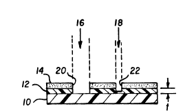
illustrated in Fig. 1. A plastic support, such as a
! J ~ ~ ~
-11-
white polystyrene slide 10, has an intermediate layer
12 coated thereon, and a black coating 14 is applied
thereover. A laser, not shown, is used to send
- beams, arrows 16 and 18, through a mask, not shown,
to remove portions 20, 22 from coating 14. In
addition, all of the layer 12 underlying portion 20
was removed, but only a portion of layer 12 is
removed by the laser under portion 22. Thus, some of
the plastic 10 is exposed to the action of laser beam
16. However, the thickness "t" of layer 12 is
selected to prevent any significant distortion of
plastic 10. As noted, "t" is at least sufficient to
give a dried coverage of about 1.5 g/m2.
In addition to the process noted above, it
is a preferred option to ablate coating 14, Fig. 1,
in such a way as to minimize the amount of dust and
dirt from coating 14 that falls back onto white or
clear layer 12. That is, there tends to be a
scattering, during laser ablation, of the parts of
coating 14, which ends up as smudges, dirt or
discoloration on the white or transparent layer 12.
The process for correcting this is illustrated in
Fig. 2. Parts similar to those previously described
bear the same reference numeral to which the
distinguishing suffix A is applied.
That is, a black stripe 14A is applied as a
coating to any suitable support lOA (with or without
an intermediate layer as described above). The
support is white, so that any debris that falls
outside the black stripe will be noticeable. The bar
code 30 or other marking is formed widthwise across
the stripe, so that laser ablation using prior art
techniques stops just outside the edges of the A ~4~~
stripe. That is, the laser operates~on ~ for a
distance "x". However, in accord with the invention
the mask used with the laser provides for additional
$3 ` ~
. _
-12-
ablation in the areas 32 and 34 outlined by a dotted
line. Thiæ includes a dimension "y" that preferably
exceeds the height y' of the bar code 30. It is
important that areas 32 and 34 at least touch ~tripe
14A, and preferably, overlap the stripe. As a
result, any debris that might fall into area 32 or 34
is ablated away. Preferabl~, the width of each of ~ k~
areas 32~and 34 is about ~m and the height y is Al~c
about ~mm. For comparison, y' is typically ~ Y~'~
only ~ .~ y /qC
Fig. 3 illustrates the prior art approach.
The number "11~ is ablated by laser in black strip
40, leaving large black border areas 42 all around
the marking. As a result, the number cannot be
formed close to the edge of the stripe, and much area
is wasted in the bo}ders.
The invention has been described in
detail with particular reference to certain preferred
embodiments thereof, but it will be understood that
variations and modifications can be effected within
the spirit and scope of the invention.