Sélection de la langue

Search

Sommaire du brevet 2033663 

Énoncé de désistement de responsabilité concernant l'information provenant de tiers

Une partie des informations de ce site Web a été fournie par des sources externes. Le gouvernement du Canada n'assume aucune responsabilité concernant la précision, l'actualité ou la fiabilité des informations fournies par les sources externes. Les utilisateurs qui désirent employer cette information devraient consulter directement la source des informations. Le contenu fourni par les sources externes n'est pas assujetti aux exigences sur les langues officielles, la protection des renseignements personnels et l'accessibilité.

Disponibilité de l'Abrégé et des Revendications

L'apparition de différences dans le texte et l'image des Revendications et de l'Abrégé dépend du moment auquel le document est publié. Les textes des Revendications et de l'Abrégé sont affichés :

  • lorsque la demande peut être examinée par le public;
  • lorsque le brevet est émis (délivrance).
(12) Demande de brevet: (11) CA 2033663
(54) Titre français: PLATEAU MAGNETIQUE
(54) Titre anglais: MAGNETIC TOP
Statut: Réputée abandonnée et au-delà du délai pour le rétablissement - en attente de la réponse à l’avis de communication rejetée
Données bibliographiques
Abrégés

Abrégé anglais


Novelty Magnet Top
Abstract of the Disclosure
A permanent magnetic top is arranged to rotate on one or more
surfaces, of a toy induction turret, which are in close proximity
to a coil. An electric circuit is arranged to switch the coil in
such a manner so as to accelerate the top. A handle is connected
to the turret so that the top maybe skillfully transferred from
one surface to another. In one version it is arranged to generate
a tone or musical notes when the top is spinning.

Revendications

Note : Les revendications sont présentées dans la langue officielle dans laquelle elles ont été soumises.


The embodiments of the invention in which an exclusive property
or privilege is claimed are defined as follows:
1 A novelty magnetic toy having a stator coil and an electric
circuit, a magnetic top, supporting means for the top in close
proximity to and external of the coil for supporting the top for
rotation relative to an external of the coil, a source of electric
potential in the electric circuit and means in the electric circuit
operable by the coil current induced by rotation of the magnetic
top for momentarily connecting the source of electric potential
across the coil to momentarily impose a magnetic field on the
magnetic top to accelerate rotation thereof, the supporting means
mounted externally on a head which contains the coil, a shank
connected to the head, wherein the shank is arranged to form a
handle.
2 A novelty magnetic toy having a stator coil and an electric
circuit, a magnetic top, a multitude of supporting means for
supporting the top in close proximity to and external of the coil
for rotation relative to and external of the coil, a source of
electric potential in the electric circuit and means in the
electric circuit operable by the coil current induced by rotation
of the magnetic top for momentarily connecting the source of
electric potential across the coil to momentarily impose a
magnetic field on the magnetic top to accelerate rotation thereof,
the supporting means mounted externally on a head which contains
the coil, a shank connected to the head, wherein the shank is
arranged to form a handle.

3 The novelty magnetic toy of claim 1 comprising an electrically
operated sounder, and means to switch the sounder on activated by
means sensing the rotation of the top.
4 The novelty magnetic toy of claim 2 comprising an electrically
operated sounder, and means to switch on the sounder activated by
means sensing the rotation of the top.
The novelty magnetic toy of claim 2 comprising a sensing means
placed in close proximity to each supporting means, generator means
for generating a multitude of musical notes, said sensing means
connected to the generator means and arranged to turn on said
generator means to generate a specific musical note.
6 A novelty magnetic toy of claim 1 comprising a music generator
arranged to be switched on by means sensing the rotation of the top.
7 The novelty magnetic toy of claim 2 comprising sensing means
placed in close proximity to each supporting means and means to
switch on an electrical circuit activated by said sensing means.
8 The novelty magnetic toy of claim 1 comprising a multitude of
supporting surfaces and an induction coil placed in close
proximity to each surface, a generator means for generating a
multitude of musical notes, each surface having a sensing means
for sensing the rotation of the top and each sensing means
connected to the generator and arranged to turn on said generator
to generate a specific musical note.
9 The novelty magnetic toy of claim 1 comprising a multitude of
supporting surfaces and an induction coil placed in close
proximity to each surface, sensing means placed in close proximity
to each supporting surface and means to switch on an electrical
circuit activated by said sensing means.

Description

Note : Les descriptions sont présentées dans la langue officielle dans laquelle elles ont été soumises.

Di~closure
This invention relates to a magnetic toy and more particularily
to an electric motor having a magnetic top as a rotor, in which
the top can be manipulated in a skillfull fashion.
Andrew~ United States patent 3783550 describes a novelty electric
motor compri~ing a magnetic top and an induction coil which i3
automatically energized from a battery. The spinnir!g of the top
on a concaYe surface clo~e to the coil, induce~ voltage~ in the
coil which cyclically turn~ on a transi~tor. Th8 transi~tor when
switched on connect~ the battery to the coil producing a magnetic
field whîch accelerate~ the top. The top spins on a ~oncave
~ur ace in clo~e proximity to the coil~
By attaching a handle to the combination of the coil, battery,
~ransistor and concave surface a ~urret i~ formed, on which
the top can be ~killfully manipulatedO Also by placing several
concave qurface~ in close proximity to the coil, the top maybe
thrown from one surface to another, wherein it i~ accelerated on
each urface, ~hereby keeping it spinning.
Two induction turret~ can be used to juggle two or more tops. A
sounder i~ used to produce a buzzing note or a mu~ical note when
the top spin~ on a concave surface. In one arrangem*nt it acts
a~ a musical instrument by producing a different note for aach

. --
~33~
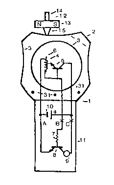
Figure 1 shows an induction turret 1 having a head 2 and a
multitude of concave su~faces 3. Inside turret 1 is an induction
coil 4 having an iron core 6. Coil 4 iq located in close proximity
to concave surfaces 3. Also located inside turret 1 are NPN
transistors 5 and 8, a 1 megohm current limiting resistor 7,.a
piezo electric sounder 9 and a bat~ery 10. A handle 11 i5 attached
to head 2.
Also shown is a top 12 comprising a disc magnet 13, with poles as
shown,a spindle 14 and a pivot 15.
Transistor 5, coil 4 and top 12 form an electric motor powered by
a battery 10, in which coil 4 is the stator and top 12 is the
rotor. When top 12 is spun on anyone of the surfaces 3, which
must be held horizontal, its rotating magnetic ~ield induces a
voltage in coil 4, which turns on transistor 5. This alternately
switches battery 10 across coil 4, producing a magnetic field
which accelerates top 12. Push pull arrangements are possible,
t'.ey would more efficently activate the coil.
By holding handle 11 the top 12 can be thrown from one concave
surface 3 and caught on another concave surface 3. The magnetic
field produced by coil 4 will power top 12 almost anywhere in a
sphere in close proximity to coil 4; therefore a multitude of
surfaces maybe located around coil 4. The top does not tend to be
powered when its axis of rotation is directly in line with core 6.
Resistor 7, transistor 8 and sounder 9 produce a sound which
emulates the speed of rotation of top 12. Transistor 8 switches
on in synchronism with tran~istor 5, both of which are driven
by coil 4. Sounder 9 produc-es a beep every time transistor 8 is
switched on. This occurs at the rate of rotation of top 12.
Figure 2 shows a 47000 ohm current limiting re~i~tor 20 in series
with a diode 21. Diode 21 i9 connected to a 1 megohm resistor 22,
a 1 mfd capacitor 23 and an NPN tran~i~tor 24. Relay 25's coil
is connected in aeries ~ith ~he collector of transi3tor 24. It~
con~act~ are connected to swi~ch on a device 26. Device 26 can be
an electronic music generator, a light, logic circuitry to play
games, etc.

~$~
Points A B and C of figure 2 are connected to points A B and C of
figure l. Items 7, 8 and 9 of figure l are deleted.
When top 12 spins a voltage is generated in coil 4 which is
rectified by diode 21 charging capacitor 23, turning on transi tor
24 which activates relay 25. Relay 25 turns on device 26.
~igure 3 shows a sensing coil 31 connected to a lO mfd capacitor
30,a 330000 ohm bias resistor 32 and the base of NPN transistor
33. The collector of transistor 33 is connected to a 33000 ohm
re~istor 34 and a a. l mfd capacitor 35. Capacitor 35 is connected
to diodes 36 and 37. Diode 37 is connected to a 1 megohm resistor
38, a l mfd capacitor 39 and to the base of PNP transistor 40.
The collector of transistor 40 is connected to a 25000 ohm
variable resistor ~l.
The circuit compei3ing items 30 to 41 is repeated
as many times as musical notes that are required. They all
connect their variable resistor 41 to point x at the junction of
unijunction transistor 43 and the 0.01 mfd capacitor 42~
Transistor 43 is connected to lO0 ohm resistors 44 and 45. The
base of transistor 47 is connected to the junction of resistor 45
and transistor 43. The collector of transistor 43 is connected to
a 1000 ohm resistor 46 and transducer 48. A battery 49 i5 used to
power transistors 33, 40, 43 and 47.
A sensing coil 31 is placed close to each concave surface 3 of
figure l. When top 12 rotates close to a coil 31 it induces an
alternating voltage in it, which is amplified by transistor 33
and i~ rectified by rectifiers 36 and 37, charging capacitor 39.
This will turn on transistor 40 connec~ing resistor 41 to the ~
battery connection. This will cause transistor 43 to o~cillate at a
frequency dependent upon the resistance of resistor 41 and the
capacitance of capacitoe 42. Transistor 47 amplifiers this tone
which is heard in transducer 48.

2 ~ 3 3 6 ~ ;~
Since foc each surface 3 itemq 30 to 41 are repeated, a different
tone maybe generated dependent upon the setting of resi~tor 41.
These tones maybe adjusted to provide a musical scale. A tune maybe
played by throwing the top from one surface 3 and catching it on
another appropriate surface 3.
Figure 4 shows a head 50 of an induction turret having a multitude
of concave surfaces 51 and a multitude of induction coil~ 52. A
handle 53 is connected to head 50O
Figure 5 shows a coil 52 , having an iron core 54, connected to an
NPN transistor 55. The junction of coil 52 and the base of
transistor 55 iq connected to a 47000 ohm current limiting resistor
56 and diode 57. Diode 57 is connected to the parallel combination
of 1 megohm resistor 59, 1 mfd capacitor 60 and the base of
tran~istor 61. The collector of transistor 61 is connected to a
pieæo electric tone generator 58. A battery 62 i~ connected to
transistors 55 and 61. This is repeated as many times as there are
induction coils.
The functions of items 54 and 55 are the same as items 4 and 5 of
of figure 1. Voltage~ induced in coil 52 by the ~pinning of top 12
in close proximity to it are rectified by diode 57 and charge
capacitor 60 , thereby sensing the rotation of the top. This turns
on transistor 61, activating tone generator 58~ Each tone generator
53 is tuned to a different frequency and can therefore be used to
provide a variety of musical notes. ~ tune can be played by
throwing the spinning top 12 from one surface 51 to another
appropriate surace 51.
It is to be understood that the form of the invention herein
shown and described is to be taken as the preferred example
of the same and that various changes in shape size and arrangement
of parts maybe resocted to without departing from the spirit of
the invention or the scope of the subjoined claims.

Dessin représentatif
Une figure unique qui représente un dessin illustrant l'invention.
États administratifs

2024-08-01 : Dans le cadre de la transition vers les Brevets de nouvelle génération (BNG), la base de données sur les brevets canadiens (BDBC) contient désormais un Historique d'événement plus détaillé, qui reproduit le Journal des événements de notre nouvelle solution interne.

Veuillez noter que les événements débutant par « Inactive : » se réfèrent à des événements qui ne sont plus utilisés dans notre nouvelle solution interne.

Pour une meilleure compréhension de l'état de la demande ou brevet qui figure sur cette page, la rubrique Mise en garde , et les descriptions de Brevet , Historique d'événement , Taxes périodiques et Historique des paiements devraient être consultées.

Historique d'événement

Description Date
Inactive : CIB désactivée 2020-02-15
Inactive : CIB attribuée 2019-06-21
Inactive : CIB en 1re position 2019-06-21
Inactive : CIB expirée 2019-01-01
Demande non rétablie avant l'échéance 1996-07-07
Le délai pour l'annulation est expiré 1996-07-07
Inactive : Demande ad hoc documentée 1996-01-08
Réputée abandonnée - omission de répondre à un avis sur les taxes pour le maintien en état 1996-01-08
Demande publiée (accessible au public) 1992-07-08

Historique d'abandonnement

Date d'abandonnement Raison Date de rétablissement
1996-01-08
Titulaires au dossier

Les titulaires actuels et antérieures au dossier sont affichés en ordre alphabétique.

Titulaires actuels au dossier
THOMAS A. WATSON
Titulaires antérieures au dossier
S.O.
Les propriétaires antérieurs qui ne figurent pas dans la liste des « Propriétaires au dossier » apparaîtront dans d'autres documents au dossier.
Documents

Pour visionner les fichiers sélectionnés, entrer le code reCAPTCHA :


Pour visualiser une image, cliquer sur un lien dans la colonne description du document. Pour télécharger l'image (les images), cliquer l'une ou plusieurs cases à cocher dans la première colonne et ensuite cliquer sur le bouton "Télécharger sélection en format PDF (archive Zip)" ou le bouton "Télécharger sélection (en un fichier PDF fusionné)".

Liste des documents de brevet publiés et non publiés sur la BDBC .

Si vous avez des difficultés à accéder au contenu, veuillez communiquer avec le Centre de services à la clientèle au 1-866-997-1936, ou envoyer un courriel au Centre de service à la clientèle de l'OPIC.


Description du
Document 
Date
(aaaa-mm-jj) 
Nombre de pages   Taille de l'image (Ko) 
Abrégé 1992-07-07 1 12
Revendications 1992-07-07 2 79
Dessins 1992-07-07 1 29
Description 1992-07-07 4 160
Dessin représentatif 1999-04-11 1 10
Taxes 1993-02-24 1 35
Taxes 1993-01-14 1 30
Correspondance 1994-04-26 1 24
Taxes 1992-02-24 3 176
Taxes 1994-02-22 1 15
Correspondance 1993-02-09 2 35
Correspondance 1993-03-16 1 16