Sélection de la langue

Search

Sommaire du brevet 2035501 

Énoncé de désistement de responsabilité concernant l'information provenant de tiers

Une partie des informations de ce site Web a été fournie par des sources externes. Le gouvernement du Canada n'assume aucune responsabilité concernant la précision, l'actualité ou la fiabilité des informations fournies par les sources externes. Les utilisateurs qui désirent employer cette information devraient consulter directement la source des informations. Le contenu fourni par les sources externes n'est pas assujetti aux exigences sur les langues officielles, la protection des renseignements personnels et l'accessibilité.

Disponibilité de l'Abrégé et des Revendications

L'apparition de différences dans le texte et l'image des Revendications et de l'Abrégé dépend du moment auquel le document est publié. Les textes des Revendications et de l'Abrégé sont affichés :

  • lorsque la demande peut être examinée par le public;
  • lorsque le brevet est émis (délivrance).
(12) Demande de brevet: (11) CA 2035501
(54) Titre français: RACCORDS ETANCHES POUR CANALISATIONS SERVANT AU TRANSPORT DES FLUIDES
(54) Titre anglais: FLUID-TIGHT CONNECTORS FOR FLUID-CARRYING PIPE-LINES
Statut: Morte
Données bibliographiques
(52) Classification canadienne des brevets (CCB):
  • 285/53
(51) Classification internationale des brevets (CIB):
  • F16L 19/08 (2006.01)
  • F16L 19/00 (2006.01)
(72) Inventeurs :
  • CHAUVEL, MICHEL (France)
(73) Titulaires :
  • CHAUVEL, MICHEL (Non disponible)
  • SIMMONDS S.A. (France)
(71) Demandeurs :
(74) Agent: OSLER, HOSKIN & HARCOURT LLP
(74) Co-agent:
(45) Délivré:
(22) Date de dépôt: 1991-02-01
(41) Mise à la disponibilité du public: 1991-08-06
Licence disponible: S.O.
(25) Langue des documents déposés: Anglais

Traité de coopération en matière de brevets (PCT): Non

(30) Données de priorité de la demande:
Numéro de la demande Pays / territoire Date
90 01 303 France 1990-02-05

Abrégés

Abrégé anglais


ABSTRACT OF THE DISCLOSURE

A pipe connector comprising two members with
respectively concave and convex mating co-operating ends and
fitting together by an internally threaded sleeve retaining one
of the members and tightened by being screwed onto the outer
threading of the other member, this outer threading being
extended by a threaded portion having a greater diameter than
and the same pitch as those of the outer threading and being
adapted to co-operate with a lock washer retained in a recessing
formed in one of the ends of the sleeve.

Revendications

Note : Les revendications sont présentées dans la langue officielle dans laquelle elles ont été soumises.


The embodiments of the invention, in which an exclusive property
or privilege is claimed are defined as follows.


1. A fluid-tight connector for fluid-carrying pipe-
lines, of the type comprising two members with respectively
convex and concave mating co-operating ends and joined together
by an internally threaded sleeve retaining one of the members
and tighten by being screwed onto an external threading provided
on the other member, wherein the improvement consists in that
the outer threading of the other member is extended by a
threaded portion which has a greater diameter than that of the
external threading and which is adapted to co-operate with a
self-locking washer kept in a recessing formed in the sleeve,
following the threaded inner portion of this sleeve and the
inner periphery of which has a greater diameter than that of the
threaded inner portion of the sleeve.
2. A connector according to claim 1, wherein said
threaded portion and the external threading of the other member
have the same pitch.


Description

Note : Les descriptions sont présentées dans la langue officielle dans laquelle elles ont été soumises.

~` 203~01

-1-

The present invention relates essentially to an improved
fluid-tight connector or like fitting for pipe-lines for
conveying an~- fluids whatsoever such for instance as fuel for a
combustion engine.
There are already known fluid-tight connecting or
coupling devices for pipe-lines essentially comprising two parts
with respectively convex and concave co-operating, mating or
complementary ends, these two parts being joined together by an
inside threaded sleeve retaining one of the parts and tightened
by being screwed onto the other part.
In such connectors, couplers or like fittings the
locking after screwing and tightening of the sleeve was
generally provided by a locking wire extending through the
connector and therefore exhibiting inconveniences. When indeed
the connector undergoes vibrations or other forces or stresses
the locking wire may break and therefore become inoperative so
that the locking of the various parts forming the connector is
far from being perfect. This means that the connector would
become untightened with all the possible troublesome
consequences resulting therefrom and among which may be
mentioned the risks of substantial leaks and the fire hazards in
the case where the pipe-lines coupled together provide for the
flow of fuel. The object of the present invention is to cope in
particular with these drawbacks by providing an improved
fluid-tight connector, coupler or like fitting which always
remains in locked position whatever the stresses or forces it
undergoes may be and the mounting or assembly of which remains
simple, convenient and quick~
For that purpose the subject matter of the invention is
3 an improved fluid-tight connector for pipe-lines carrying any
fluids whatsoever and of the type comprising two parts with
respective convex and concave co-operating mating or
complementary ends and joined together by an inside threaded
sleeve retaining one of the parts and tightened by being screwed
onto the outer threading provided on the other part,
characterized in that the outer threading of the other part is

2~3~


extended by a threaded portion which has a greater diameter than
that of said ou-ter threading and which is adapted to co-operate
with a self-locking or self-stopping washer kept in a recessing
formed in the sleeve following the inner threaded portion of
this sleeve and the inner periphery of which has a greater
diameter than that of the inner threaded portion of the sleeve.
According to a preferred embodiment the aforesaid
threaded portion and the outside threading of the aforesaid
other part have a same pitch or thread.
The invention will be better understood and further
objects, characterizing features, details and advantages thereof
will better appear as the following explanatory description
proceeds wich reference to the accompanying diagrammatic
drawings give by way of non limiting example only illustrating
one presently preferred specific embodiment of the invention and
wherein:
- Figure 1 is a perspective view of a connector
according to the invention in the mounted and tightened
position;
- Figure 2 is a perspective exploded view of this
connector;
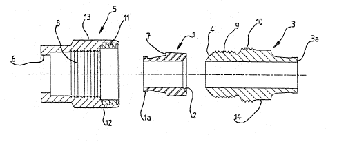
- Figure 3 is an exploded view in axial section of said
connector; and
- Figure 4 is a view in axial section of the connector
in the mounted and tightened position as on Figure 1.
According to the exemplary embodiment shown on the
Figures a fluid-tight connector according to this invention
essentially comprises a first member 1 with a concave end 2, a
second member 3 with a convex end 4 mating with or complementary
of the concave end 2 of the first member 1 and a sleeve 5
externally coaxial or concentric with the members 1 and 3 and
allowing both members to be tightened against each other in
end-to-end relationship with their mating convex and concave
ends. The sleeve 5 as well seen on Figures 3 and 4 comprises at
one of its ends a coliar 6 adapted to hold back the first member
1 which for that purpose is formed with a shoulder 7 and this

~3~

--3--

sleeve comprises substantialiy at its middle portion an
internally threaded portion 8 allowing it to be screwed onto the
external threading 9 provided at the end of` the second member 3.
According to the invention this external threading 9 is
extended by a threaded portion 10 which as well sho~n on Figures
3 and 4 has a greater diameter than that of' said threading 9 and
the same thread or pitch than that of the threading 9.
The additional threaded portion 10 of the member 3 may
co-operate with a locking washer 11 made from a suitable
synthetic material such as a material known under the trademark
"VESPEL" or which is polyamide- based and kept in a recessing 12
formed within the end of the sleeve 5 opposite to the end
comprising the collar 6.
As well shown in particular on Figures 3 and 4 the
recessing 12 follows the threaded inner portion 9 of the sleeve
and the inner periphery of this recessing has a greater
diameter than that of said threaded inner portion 8 of said
sleeve 5.
According to a preferred embodiment the external
threading 9 of the member 3 and the threaded portion 10 which in
a way extends this threading necessarily comprise a same pitch
or thread.
The sleeve 5 comprises on its outside periphery and
according to the example shown flat sides 13, for instance six
flat sides allowing it to be operated by a wrench or spanner and
: likewise the member 3 also comprises flat sides beyond the
threaded portion 10 and designated at 14.
As known per se both pipes (not shown) to be connected
or coupled together through the agency of the connector
according to the invention will be secured with their ends and
for instance through welding onto the end 1a of the member 1 and
onto the end 3a of the member 3, respectively.
For an easier understanding of the invention there will
now be set forth hereinafter how the mounting or the assembly
and the tightening of the connector just described will be
carried out.

5 ~ J


The first member 1 being at first inserted into the
sleeve 5 the member 3 will be screwed into the sleeve 5 and this
by means for instance of a wrench or a spanner caused to be
engaged with the flat sides 13 and/or 14.
After a screwing stroke of some length the externally
threaded portion 10 of the member 3 will engage the locking
washer 11 previously accommodated or housed within the recessing
12 and the screwing will be continued until the convex and
concave ends 2 and 4 of the members 1 and 3 are caused to come
in abutment against each other, respectively, as well shown on
Figure 4. The locking of both members 1 and 3 assembled
end-to-end by the sleeve 5 will then be performed and this
locking is not at all likely to be impaired under the effect of
any stresses or forces whatsoever exerted upon the connector
owing to the provision of the self~locking washer 11 between the
sleeve 5 and the member 3.
It should be pointed out that on account of the location
: of the threaded portion 10 recessed or set back with respect to
the threaded portion 9 of the member 3, this member 3 may be
easily and freely inserted into the sleeve 5 for screwing
purposes and this member 3 will in a way be guided while being
screwed into the sleeve 5 so that the threaded portion 10 will
be caused to properly engage the locking washer 11.
It should be understood that the invention is not at all
limited to the embodiment described and illustrated which has
been given by way of example only.
On the contrary the invention comprises all the
technical equivalents of the rmeans described as well as their
cornbinations if the latter are carried according to its gist and
within the scope of the appended claims.

Dessin représentatif
Une figure unique qui représente un dessin illustrant l'invention.
États administratifs

Pour une meilleure compréhension de l'état de la demande ou brevet qui figure sur cette page, la rubrique Mise en garde , et les descriptions de Brevet , États administratifs , Taxes périodiques et Historique des paiements devraient être consultées.

États administratifs

Titre Date
Date de délivrance prévu Non disponible
(22) Dépôt 1991-02-01
(41) Mise à la disponibilité du public 1991-08-06
Demande morte 1994-08-01

Historique d'abandonnement

Il n'y a pas d'historique d'abandonnement

Historique des paiements

Type de taxes Anniversaire Échéance Montant payé Date payée
Le dépôt d'une demande de brevet 0,00 $ 1991-02-01
Enregistrement de documents 0,00 $ 1991-07-24
Taxe de maintien en état - Demande - nouvelle loi 2 1993-02-01 100,00 $ 1993-01-21
Titulaires au dossier

Les titulaires actuels et antérieures au dossier sont affichés en ordre alphabétique.

Titulaires actuels au dossier
CHAUVEL, MICHEL
SIMMONDS S.A.
Titulaires antérieures au dossier
S.O.
Les propriétaires antérieurs qui ne figurent pas dans la liste des « Propriétaires au dossier » apparaîtront dans d'autres documents au dossier.
Documents

Pour visionner les fichiers sélectionnés, entrer le code reCAPTCHA :


Pour visualiser une image, cliquer sur un lien dans la colonne description du document. Pour télécharger l'image (les images), cliquer l'une ou plusieurs cases à cocher dans la première colonne et ensuite cliquer sur le bouton "Télécharger sélection en format PDF (archive Zip)" ou le bouton "Télécharger sélection (en un fichier PDF fusionné)".

Liste des documents de brevet publiés et non publiés sur la BDBC .

Si vous avez des difficultés à accéder au contenu, veuillez communiquer avec le Centre de services à la clientèle au 1-866-997-1936, ou envoyer un courriel au Centre de service à la clientèle de l'OPIC.


Description du
Document 
Date
(yyyy-mm-dd) 
Nombre de pages   Taille de l'image (Ko) 
Dessins représentatifs 1999-08-19 1 11
Dessins 1991-08-06 2 47
Revendications 1991-08-06 1 27
Abrégé 1991-08-06 1 18
Page couverture 1991-08-06 1 15
Description 1991-08-06 4 198
Taxes 1993-01-21 1 47