Note : Les descriptions sont présentées dans la langue officielle dans laquelle elles ont été soumises.
2~5~r~
FIELD OF THE INVENTION
The present invention relates to a glass lifting
device which can be used in doors of various vehicles,
whatever the design of the carriage body of this vehicle.
BACXGROI~ID OF THE INVENTION
It should first be recalled that till now, the
glass lifting devices of the door of vehicle which -
included a set of arms were divided into two main
sections, namely :
- the glass lifting devices with rigid arms for
glasses of plane windows,
- the glass lifting devices with flexible arms
for glasses of curved windows thereby enabling, due to
their flexibility, a following of the curvature of the
lS glass side guides.
When these solutions cannot be used, it is
necessary to use, in the doors of automobile vehicles,
driving mechanisms for lifting or lowering the glasses
which include assemblies of cables with return pulleys,
or assemblies of offset spiral springs for driving the
glass upwardly or downwardly via pinions meshing with
turns of each spring.
The above description, which pertains to the
prior art, shows obviously that it was necessary each
time to make a particular study of the device since no
solution was a standard solution. Where flexible arms
were used, a resistance due to the flexion of the arms
was felt on account of the tor~ue thus created which was
,
. '. ~ .
2~3~52~
acting on the control crank. In the case of cables or
push springs, the guiding operation was very hazardous
because of the fixation points, either of the cable or of
the spring, on a center of the glass or at a lower end of
the glass support.
The present invention remedies this disadvantage
by providing a glass lifting device which very easily
adapts itself to all cases.
SUMMAR~ OF THE INVENTION
According to the invention, the glass lifting
device comprises a platen fixed on an armature of a
vehicle door in consideration and carries, at one of its
ends, a shaft for rotation of a pinion which meshes with
a toothing of a sector causing a rotation about a pin of
this sector, this sector being extended, at a lower
portion, by a toothed half-moon for cooperating with a
toothing of another toothed half-moon also mounted on a
pin, these two pins being placed in a same horizontal
plane perpendicular to the platen for supporting a set of
arms, a driving in rotation of these arms being provided
for each of the arms by a spindle rigidly connected to
the toothed half-moons, and finally a front face of the
pins is inclined by an angle a with respect to a vertical
~urface of the platen, whereby the arms are arranged in
planes for an appropriate guiding in height (lifting and
lower~ng) of a curved glass of the vehicle door~
.:
.
, ~ - .
,
3~2~zj ,
Various other features of the invention will
become more apparent from the following detailed ;
description.
BRIEF DESCRIPTION OF THE DRAWINGS
. _
An embodiment of the invention is shown, by way
of a non limiting example, in the accompanying drawings,
wherein :
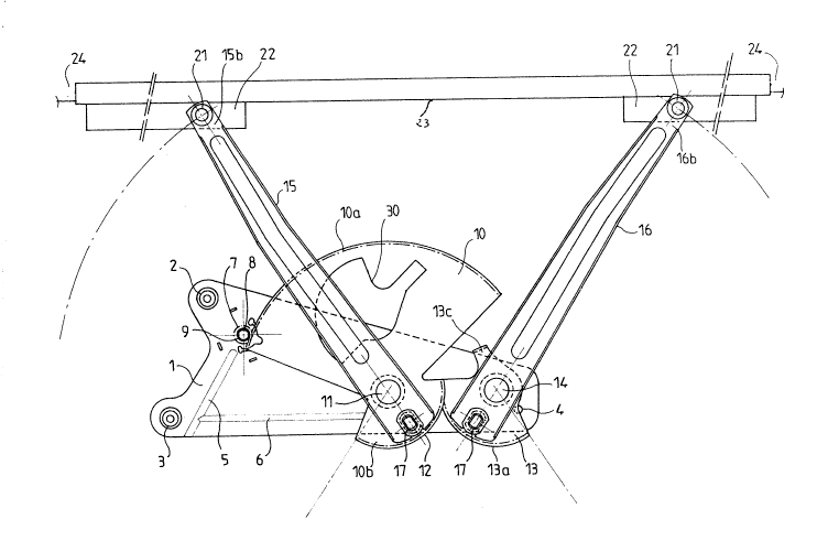
Fig. 1 is a front elevation view of the glass
lifting device according to the invention ;
Fig. 2 is a plan view, partly in cross-section,
corresponding to Fig. 1 ;
Fig. 3 shows an enlarged detail of the device for
maintaining the glass on the lifting arm ;
Fig. 4 is an enlarged cross-sectional view of one
of the members of the glass lifting device.
DESCRIPTION OF THE PREFERRED EMBODIMENT
Referring now to Fig. 1, a platen 1 substantially
in the shape of a rectangular trapezium is fixed at 2, 3,
4 on an inner armature of a vehicle door. This platen 2,
which is rigidified by embossed lines 5, 6, carries a
bearing member 7 in which can rotate a shaft 8 driving a
pinion 9 which meshes normally with a toothing lOa of a
toothed sector 10 mounted on a pin 11 rigidly connected
to the platen 1. The toothed sector 10 is extended, at
its lower portion, by a semi-circular half-moon lOb
having a toothing 12 so as to cooperate with a toothing
13a of a second toothed half-moon 13 of same diameter as
the toothed half-moon lOb and mounted on a fixed pin 14 -
.,, . . ~ . .
~: '
, ~ .
~ 3
rigidly connected to the right hand side portion of the
platen 1. The toothing 13a is identical to the toothing
12.
Thus, when the pinion 9 is driven by means of the
S shaft 8, the pinion 9 imparts, by meshing with the
toothing lOa of the toothed sector 10, a rotary motion of
the toothed sector 10 about the fixed pin 11. The rotary
motion of the toothed sector 10 drives the half-moon lOb
which meshes with the toothing 13a of the second
half-moon 13.
Arms 15, 16 are mounted on the pins 11 and 14,
the arm 15 being connected to the half-moon lOb and the
arm 16 beinq connected to the half-moon 13. The junction
between the pins 15 and lh and the half moons lOb, 13 is
effected by means of spindles 17 fixed on the outer
periphery of the half-moons lOb, 13 via two plates 18, 19
(see Fig. 4). The spindles 17 have in cross-section a
shape which is substantially rectangular, and they are
connected to bottom of the arms 15, 16 by means of rings
29 introduced inside holes 20 formed in the arms 15, 16.
The rings 29 are generally made of a plastics
material, and more especially of a greasy synthetic
material. The rings 29 have a central opening 29a with a
hemispherical edge so as to facilitate their introduction
on the spindles 17 and, also, to provide a slight
clearance so that the arms 15, 16 will occupy a position
adapted to the curvature of glasses of the vehicle door ;
this being completed by the fact that the fixed pins 11
.~
and 14 have in cross-section (see Fig. 2) a shape of a
rectangular trapezium, the front face lla, 13a of each of
which is inclined and forms and angle a (see fig. 2)
corresponding there again to the curvature of the glass
in question. In general, the pins 11 and 14 are made of a
cast material and the angle is between 1 and 25, and
preferably between 6 and 15.
Finally, the upper end 15b, 16b of the arms 15,
16 carries rollers 21, with the rollers 21 sliding inside
guides 22 (see Fig. 1). A U-shaped clamp 23 (see Fig. 3)
is provided for maintaining the curved glass 24 in
consideration rigidly on the arms 15, 16.
The shaft 8 which carries the pinion 9 can be
motorized in some cases.
As may be seen easily in Fig. 1, the upper end
13c of the half-moon 13 is bent at a right angle so as to
limit the movement of the half-moons lOb, 13 in order to
allow a maximum lowering of the glass in consideration
and also to avoid a disengagement of the cooperating
toothings 12 and 13a of these two half-moons. Moreover,
there is provided a spiral spring 31 (Fig. 2) which, by
acting on the end 13c of the half-moon 13, balances the
forces of reaction of the mechanical assembly forming the
glass lifting device.
~t should also be pointed out that the half-moon
12 can be cut out, for reasons of economy, by any
convening means in the central portion of the sector 10,
~ ~ 3 ~
that the sector 10 is made lighter due to a corresponding
opening 30 ~see Fig. 1).
: