Note : Les descriptions sont présentées dans la langue officielle dans laquelle elles ont été soumises.
~03~~~~-
BACKGROUND OF THE INVENTION
The present invention relates to the provision of firm stable three-
dimensional expanded structures, that are capable of being collapsed
down to compact bundles.
There are many times when one wishes to have an enclosure at a
remote site and, rather that transport it to such site, one transports it
in some collapsed form. Thus, a tent is folded up, transported and
erected where needed. A fabric tent, however, has no rigidity and it is
therefore necessary to utilize tent poles, pegs and rope to give the
tent some degree of rigidity. Further, it must be set on a reasonably
firm sub-surface.
Pneumatically inflatable enclosures are another option for such a
portable enclosure, but again substantial preparation is required.
The present invention provides reasonably rigid three dimensional
enclosures that may be readily collapsed and expanded. These
structures are made up of units which are comprised of facets that are
connected by pleats or hinges. This invention has many desirable
characteristics:
First, they fold down to a very compact bundle. Given the size of the
structure's basic facet, the collapsed structure will essentially consist
of a stack whose area is the size of fihat facet and whose height is the
sum of the thicknesses of all the facets in the structure.
Second, it is possible to construct a wide variety of shapes and forms
utilizing this method. Illustrated herein are such shapes as planes,
cylindrical sections, cones, tent shapes, and doubly curved surfaces.
This variety of forms allows for many different uses.
(2)
~~3~~ 4~.
Third, many of the forms and shapes that can be made may be
constructed from a single flat sheet of material that is scored or
pleated. Because only a single flat sheet is required, many low cost
manufacturing techniques may be employed, such as stamping, simple
molds, etc.
Fourth, this method allows for utilizing materials of finite thickness.
Plastics, wood, metal and other rigid materials may be employed for
malting structures that require more permanance and rigidity.
(3)
203~~~~.
BRIEF BURY OP' TFiE INVENTIQN
Self supporting structures of di~rerae shapes are disclosed that may be
collapsed down to a compact bundle, Structures of this bind are
comprised by units which are comprised of eentwal tapered strips that
are bordered by elongated strips. By pleating these strips according to
a special pattern, the structure may collapse down and expand out in a
smooth mamner.
2Q~~~~~.
BRIEF DESCRIPTION OF THE DRAWING FIGURES
The invention will be further described with reference to the
accompanying .drawin fs, wherein:
Fig. 1 is a plan view showing the basic unit of the invention;
Figs. 2-4 are perspective views of the unit shown in Fig. 1, as it is
folded down to its fully collapsed state;
Fig. 5 is a plan view showing an alternate embodiment of the basic unit
of the invention;
Figs. 6-8 are perspective views of the unit shown in Fig. 5, as it is
folded down to its fully collapsed state;
Fig. 9 is a plan view of a planar structure that is an embodiment of the
invention;
Figs. 10-12 are perspective views of the structure shown in Fig. 9 as it
is folded down to its fully collapsed state;
Fig. 13 is a plan view of a cylindrical structure that is an embodiment
of the invention;
Figs. 14-16 are perspective views of the structure shown in Fig. 13 as
it is folded down to its fully collapsed state;
Fig. 17 is a plan view of a tent-shaped structure that is an embodiment
of the invention;
Figs. 18-20 are perspective views of the structure shown in Fig. 17 as
it is folded down to its fully collapsed state;
Fig. 21 is a plan view of a structure having an S-type curvature that is
an embodiment of the invention;
Figs. 22-24 are perspective views of the structure shown in Fig. 21 as
it is folded down to its fully collapsed state;
Fig. 25 is a plan view of a conical structure that is an embodiment of
the invention;
Figs. 26-28 are perspective views of the structure shown in Fig. 25 as
it is folded down to its fully collapsed state;
Figs. 29-32 are perspective views of the structure having double
curvature as it is folded from its fully developed state to its fully
collapsed state;
(5)
203~~~~.
Fig. 33-35 are perspe~aive views showing an alternate construction of
the basic unit of the invention, utilizing hinged rigid plates;
Fig. 36-38 are views showing an alternate construction of the basic
structural unit of the invention and that utilizes a flexible sheet with
stiffening framing members;
Fig. 39 shows an alternate pattern for the basic unit where the central
strip is tapered in a step-like fashion.
(6)
~~3~~~.~
DETAILED DESCRIPTION
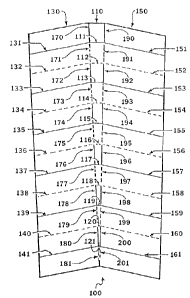
Referring now more particularly to the drawings, in Fig. 1 there is
shown a unit 100 comprised of a central tapered strip 110 which is
bordered by two elongated strips 130 and 150. Tapered strip 110 is
pleated along a series of crossing lines 111-121 that cross it
widthwise. The fold directions of adjacent crossing lines alternate.
Elongated strip 130 is pleated along a series of crossing lines 131-141
that cross it widthwise. The fold direction of adjacent crossing lines
alternate. Crossing line 131 is essentially a continuation of crossing
line 111. Similarly, crossing lines 132-141 are essentially
continuations of crossing lines 112-121 respectively.
Elongated strip 150 is pleated along a series of crossing lines 151-161
that cross it widthwise. The fold direction of adjacent crossing lines
alternate. Crossing line 151 is essentially a continuation of crossing
line 111. Similarly, crossing lines 152-161 are essentially
continuations of crossing lines 112-121 respectively.
Central tapered strip 110 is connected to elongated strip 130 along a
series of connecting pleat lines 170-181 that are connected end to
end. The fold direction of adjacent connecting lines 170-181
alternate. Similarly, central tapered strip 110 is connected to
elongated strip 150 along a series of connecting pleat lines 190-201
that are connected end to end. The fold direction of adjacent
connecting lines 190-201 alternate. .
In Fig. 2, unit 100 is shown partially folded. Central tapered strip 110
and elongated strips 130 and 150 fold in a zig-zag fashion.
In Fig. 3, unit 100 is shown folded to a further degree than Fig. 2.
Elongated strips 130 and 150 may be seen to fold towards each other.
In Fig. 4 unit 100 is shown to be essentially completely folded.
Elongated strips 130 and 150 have each folded into a stack. The
central tapered strip 110 has folded in a zig-zag fashion, such that the
(7)
~0~~~~~.
planes of the tapered strip lie essentially orthogonal to the planes of
the stacked elongated strips 130 and 150. Stacked elongated strips
130 and 150, have folded towards each other such that the stacks lie
essentially in line with one another.
In Fig. 5 there is shown a unit 300 which is an alternate embodiment
bf the invention. It is comprised of a central tapered strip 310, which
is bordered by two elongated strips 330 and 360. Tapered strip 310 is
pleated along a series of crossing lines 311-321 that cross it
widthwise. The fold directions of adjacent crossing lines alternate.
Elongated strip 330 is pleated along a series of crossing lines 331-353
that cross it widthwise. The fold directions of adjacent crossing lines
alternate. Crossing line 331 is essentially a continuation of crossing
line 311. Similarly, crossing lines 332-353 are essentially
continuations of crossing lines 311-321.
Elongated strip 360 is pleated along a series of crossing lines 361-383
that cross it widthwise. The fold directions of adjacent crossing lines
alternate. Crossing line 361 is essentially a continuation of crossing
line 311. Similarly, crossing lines 362-383 are essentially
continuations of crossing lines 311-321.
Central tapered strip 310 is connected to elongated strip 330 along a
series of connecting pleat lines 400-411 that are connected end to
end. The fold directions of adjacent connecting lines 400-411
alternate. Similarly, central tapered strip 310 is connected to
elongated strip 360 along a series of connecting pleat lines 420-431
that are connected end to end. The fold directions of adjacent
connecting lines 420-431 alternate.
In Fig. 6, unit 300 is shown partially folded. Central tapered strip 310
folds in a zig-zag fashion.
In Fig. 7, unit 300 is shown folded to a further degree than Fig. 6.
Elongated strips 330 and 360 may be seen to fold towards each other.
f8)
~~~~~4~
In Fig. 8 unit 300 is shown to be essentially completely folded.
Elongated strips 330 and 360 have each folded into a stack. The
central tapered strip 310 has folded in a zig-zag fashion such that the
planes of the central tapered strip lie essentially orthogonal to the
planes of the stacked elongated strips 330 and 360. In Fig. 8 stacked
elongated strips 330 and 360 have folded towards each other such
that the stacks lie essentially in line with one another.
In Fig. 9 structure 500 is comprised of units 510,520 and 530. Unit
510 is comprised of central tapered strip 512 and elongated strips
514 and 516. Similarly, unit 520 is comprised of central tapered strip
522 and elongated strips 524 and 526, while unit 530 is comprised of
central tapered strip 532 and elongated strips 534 and 536. Unit 510
is connected to adjacent unit 520 by tapered strip 540 which joins
elongated strip 516 to elongated strip 524. Similarly, unit 520 is
connected to adjacent unit 530 by tapered strip 550 which joins
elongated strip 526 to elongated strip 534.
In Figs. 10 and 11 the structure 500 is shown in two partial degrees of
folding. The elongated strips 514,516,524,526,534 and 536 may be
seen to fold towards each other. Tapered strips 512,522,532,540 and
550 fold in a zig-zag fashion.
In Fig. 12 the structure 500 is shown completely folded. Elongated
strips 514, 516, 524,526, 534 arid 536 are folded into stacks which are
connected by their adjacent tapered strips. The tapered strips
512,522,532,540 and 550 are folded in a zig-zag fashion. The planes
of the tapered strips lie essentially orthogonal to the planes of the
stacked elongated strips. The stacks formed by the elongated strips lie
essentially in line with one another.
In Fig. 13 is shown a plan view of a structure 600. It is comprised of
units 610,620 and 630. Unit 610 is comprised of central tapered strip
612 and elongated strips 614 and 616. Similarly, unit 620 is
comprised of central tapered strip 622 and elongated strips 624 and
626, while unit 630 is comprised of central tapered strip 632 and
elongated strips 634 and 636. Unit 610 is connected to adjacent
(9)
~(~~~~~~.
unit 620 by tapered scrip 640, which joins elongated strip 616 to
elongated strip 624, Similarly, unit 620 is connected to adjacent unit
630 by tapered strip 650 which joins elongated strip 626 to elongated
strip 634.
In Figs. 14 and 15 the structure 600 is shown in two partial degrees of
folding, forming a structure whose shape is a cylindrical section. The
elongated strips 614,616,624,626,634 and 636 may be seen to fold
towards each other. Tapered strips 612,622,632,640 and 650 fold in
a zig-zag fashion.
In Fig. 16 the structure 600 is shown esse itially completely folded.
Elongated strips 614,616,624,626,634 and 636 are folded into stacks
which are connected by their adjacent tapered strips. The tapered
strips 612,622,632,640 and 650 are folded in a zig-zag fashion. The
planes of the tapered strips lie essentially orthogonal to the planes of
the stacked elongated strips. The stacks formed by the elongated
strips lie essentially in line with one another.
Fig. 17 shows a structure 700 comprised of two units 710 and 720,
each comprised of a central tapered strip and two elongated strips.
Units ? 10 and 720 are connected to each other by a region 730 with
an alternate folding pattern. In Fig. 18, the structure 700 is shown in a
partially folded condition, forming a tent-shaped structure. Fig. 19
shows the structure 700 folded to a further degree than Fig. 18. In Fig.
20 the structure 700 is shown essentially completely folded. .
Fig. 21 shows a structure 800 comprised of five units 810,820,830,
840 and 850, each comprised of a central tapered strip and two
elongated strips. Units 810,820,830,840 and 850 are connected to
each other by tapered strips 815,825,835 and 845. In Fig. 22, the
structure 800 is shown in a partially folded condition, forming a
structure with an S-type curvature. Fig. 23 shows the structure 800
folded to a further degree than Fig. 22. In Fig. 24 the structure 800 is
shown essentially completely folded.
( 10)
2~~~~~~
Fig. 25 shows a structure 900 comprised of five units 910,920,930,
940 and 950, each corrzprised of a central tapered strip and two
elongated strips. Units 910,920,930,940 and 950 are connected to
each other by tapered strips 915,925,935 and 945. In Fig. 26 the
structure 900 is shown in a partially folded condition, forming a
conical structure. Fig. 27 shows the structure 900 folded to a further
degree than Fig. 26. In Fig. 28 the structure 900 is shown essentially
completely folded.
Fig. 29 shows a structure 1000 having the form of a doubly curved
surface. It is comprised of three units 1010,1020 and 1030, each
comprised of a central tapered strip and two elongated strips. Units
1010,1020 and 1030 are connected to each other by tapered strips
1015 and 1025. In Fig. 30, the structure 1000 is shown in a partially
folded condition. Fig. 31 shows the structure 1000 folded to a further
degree than Fig. 30. In Fig. 32 the structure 1000 is shown essentially
completely folded.
Fig. 33 shows the unit 1100 which illustrates an alternate construction
of the invention. It is comprised by a central tapered strip 1120 which
is bordered by two elongated strips 1130 and 1140. In this
embodiment of the invention, the central strip 1120 is comprised of
rigid plates which are hingedly attached to each other. Similarly
elongated strips 1130 and 1140 are comprised of rigid plates which
are hingedly attached to each other. Central strip 1120 is hingedly
joined to elongated strips 1130 and 1140. Fig. 34 shows the unit
1100 in a partially folded state. Fig. 35 shows the unit 1100 in its fully
collapsed state.
Fig. 38 shows the unit 1200 which illustrates an alternate construction
of the invention. It is comprised by a central tapered strip 1220 which
is bordered by two elongated strips 1230 and 1240. In this
embodiment of the invention the strips 1220,1230 and 1240
comprise flexible sheets of material where the areas between pleat
lines are stiffened by rigid framing members. Fig. 37 shows the unit
1200 in a partially folded state. Fig. 38 shows the unit 1200 in its fully
collapsed state.
(11)
~o~~o~~
Fig. 39 shows the unit 1300 which is comprised by a central tapered
strip 1320 which is bordered by two elongated strips 1330 and 1340.
In this embodiment of the invention the central strip 1320 is tapered
in a step-like fashion such that the connecting lines between central
tapered strip 1320 and elongated strips 1330 and 1340 are slightly
offset from one another.
It will be appreciated that the instant specification and claims are set
forth by way of illustration and not limitation, and that various
modifications and changes may be made without departing from the
spirit and scope of the present invention.
( 12)