Note : Les descriptions sont présentées dans la langue officielle dans laquelle elles ont été soumises.
2~37~
The present invention relates to a radial ply tire ror heavy
duty use, In which s~rain generated in buttress portions Or the
tire during running is reduced to improve the durability of the
tireO
In heavy duty tires for truck, bus and the like, of which
tread portion is subjected to a large lnad,
a buttress portion or an upper sidewall part which supports
the large load is provide with a profile composed Or two arcs:
a radially Inner arc swelling outwardly of the tire and having
a center located inside of the tire on a straight line drawn
axially of the tire fro1n the tire maximum width point 1; and
a radially outer arc having a center outside the tire and
swelling lnwardly of the tire and extending from the tread edge
to the inflection point !between the two arcs,
As a result, the buttress portion is formed in a single
radius arc, and a point at which compressive strain increases
over 30 % was found.
Such compressive strain lowers the durability of the buttress
portion
Especlally when the tire has an extra heavy tread with deep tread
grooves, the compressive stress becomes very large ln the middle
part of the buttress portion since the tread rubber largely
moves axlally outwardly at the tread edges during runnlng, which
compresses the sidewall rubber In the buttress portlon~
Upon inventor's investigation Or stress dlstribution In the
buttress portion lt was found that the largest stress lles
~3~6
in a region between the above-mentioned in~lectlon point and
a point at which an axial line extended ~rom the edge Or the
widest belt ply intersects with the surrace Or the buttress
portion.
It is therefore, an object of the present invention to
provide a heavy duty radial tire, in which, by increasing the
rubber thickness in the above-mentioned region in a speciric
manner, a compressive strain generated in the buttress portion is
reduced to improve the durability.
According to one aspect Or the present lnvention, a heavy
duty radial tire comprises
a radial carcass having at least one ply cr cords extending
between bead portions through sidewall portions and a tread
portion Or the tire,
a tread disposed radially outside the carcass, and
----a--belt compris~ng at least two--plles -or~ cords- dlsposed ~ - ~~~ --
radially outside the carcass and inside the tread,
in a state that the tire is mounted on its rogular rim and
inflated to its maxlmum pressure,
the tread width between the tread edges being not less than
0.73 times the tlre maxlmum wldth (W), and .
the tlre prorlle between the tread edge and the tire maximum
section wldth point being composed Or a radially outer part
between the tread edge and a polnt Q, a radially lnner part
between the tire maximum section width point and a point R, and a
mlddle part between sald points Q and R,
the radially outer part belng a clrcular arc swelling
2~37~
in deeail with reference to the accompanying drawings, In which:
Fig.1 is a cross sectional view showing a right halr Or an
embodiment Or the present invention;
Fig.2 is a schematic cross sectionaL view explalning the
profile of the buttress portion thereor;
Fig.3 is a side view explaining a method Or measuring the
compressive strain;
Fig.4 is a graph showing a relationship between compressive
straln and positions in buttress portion; and
Fig.5 is sectional vlew showing the prior art.
Before describing the present invention a description of the
prior art in Fig. 5 will be given.
In heavy duty tires ror truck, bus and the like, Or which
tread portion is subjected to a large load, as shown in Fig.~,
a buttress portion (a) or an upper sidewall part which supports
the large load is provide with a profile composed Or two arcs:
a radially inner arc rl swelling outwardly Or the tire and having
a center located inside Or the tire on a straight line drawn
axially Or the tire rrOm the tire maximum width point m; and
a radially outer arc r2 havlng a center outside the tlre and
swelling inwardly Or the tlre and extending from the tread edge
(e) to the Inrlection polnt (r) between the two arcs rl and r2.
As a result, the buttress portion (a) is formed in a single
radius arc, and a poin t at which compressive strain increases
over 30 % was round.
Such compressive straln lowers the durability Or the buttress
portion (a).
2037~
Especlally when the tire has an extra heavy tread with deep tread
grooves, the compressive stress becomes very large ln the middle
part Or the buttress portion (a) slnce the tread rubber largely
moves àxially outwardly at the tread edges during running, which
compresses the sldewall rubber in the buttress portion.
Upon inventor's investigation Or stress distribution in the
buttress portion (a), it was round that the largest stress lies
in a region between the above-mentloned inrlectlon point (r) and
a point (c) at which an axial line extended from the edge Or the
widest belt ply b intersects with the surface of the buttress
portion.
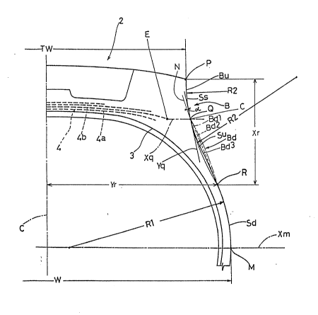
In Figs. 1-3, heavy duty radial tire 1 Or the invention
has a tread porticn 2, a pair Or axially spaced bead portions 15,
and a pair Or sidewall portions 13 extending radially inwardly
rrom the edges Or the tread portion 2 to the bead portions 15.
In a normal lnflated condition in which the tire is mounted
on its regular rim and inrlated to lts maxlmum pressure, the
tread width TW between the tread edges P is not less than 0.73
times the tire maximwn section width W.
The tire comprises a palr Or bead cores 16 dlsposed one in
each bead portion 15, a carcass 3 extending between the bead
portions 15 and turned up around the bead cores 16, tread rubber
and sidewall rubber disposed on the carcass, and a belt layer 4
disposed radially outside the carcass 3 and inside the tread
rubber.
The carcass 3 is composed Or one or rnore plies of rubberized
cords arranged radially Or the tire at angles of 90 to 30 degrees
with respect to tire equator C so as to provide for the carcass a
- 3a -
~37~
inwardly of the tlre and having a single radius of curvature ~2
and a center outside Or the tire,
the inner part being a circular arc swelling outwardly Or
the tire and havlng a single radius o~ curvature Rl and a center
positioned inward of the tire on an axial stralght line Xm drawn
from the tire maximum section width point,
the point Q located at a radial height in the range Or the
edge height of the widest ply of the belt plus or minus 5 mm,
the point R located at a radial height defined such that the
outwardly swelling circular arc of the radially inner part and
the inwardly swelling circular arc of the radially outer part
extended rrOm the point Q to the point R are smoothly connected
each other at the point R as the inflection point therebetween,
the middle part being a straight or curved line located
axially outside of the extended part of the inwardly swelling
circular arc of the radially outer part so that~the distance- -
measured from a straight line N normally to this straight line N
is not more than 2 mm, wherein the straight line N is extended
radially inwardly from the point Q toward the point R inclining
axially outwardly at an angle of 4 to 15 degrees with respect to
a tangential line to the lnwardly swelllng circular ~rc at the
point Q.
Prererably, the polnt R is located at a radlal distance,
irom the tread edge, Or 0.21 to 0.30 tlmes the tread wldth and an
axial distance, from the tire equator, Or 0.52 to 0.57 times the
tread wldth.
An embodiment of the present invention will now be described
2~7~
radial ply construction or a semiradial ply construction. In
this embodiment, the carcass ls composed of one ply of a radial
ply construction.
For the carcass cord, organic fiber cords, e.g. nylon,
polyester, rayon, aromatic polyamide and the like can be used.
The belt layer 4 is composed of at least two plies ~4a, 4b)
of parallel cords, in this example four plies of the radially
innermost first ply 4a, the second ply 4b, the third ply 4c, and
the radially outermost forth ply 4e.
The cords of each belt ply are laid at a bias angle with
respect to the tire equator C so as to cross the cords of the
next ply.
For the belt cords, steel cords and organic fiber cords,
e.g. nylon, polyester, rayon, aromatic polyamide and the like can
be used.
- The second belt ply 4b-is wider than the first belt ply 4b.
In this example, the belt plies satisfy the following condition:
2nd ply width > 1st ply width > 3rd ply width > gth ply width
That is the second belt ply 4b is wldest, and the edges thereof
are nearest to the buttress portlon.
The tread Is provided In the radially outer face 19 with
relatively deep tread groo~es 20. The tread rubber thlckness and
tread groove depths are of EHT class. (Extra Hea~y Tread
speclfied by Tlre Rim Associatlon In U.S.A.)
The profile Or the tlre in the abo~e-mentioned normal
inflated condition between the tread edge P and a tire maxlmum
section width point M (that is, a buttress part B and an upper
2~7~
sidewall part) Is determined based on a standard line Ss.
In the present in~/ention, the tire profile is treated,
eliminating lettering and decorative protrusion and indentation
and circumrerentially spaced ribs or grooves for the purpose of
prevention of scratch and the like which have no eïrect on the
behavior of the sidewall rubber, ~rom the consideration.
The standard line Ss is composed of two parts:
a radially Inner part Sd extending between the maximum section
width point M and an inflection point R, and
a radially outer part Su extending between the tread edge P and
the inflection point R.
The inner part Sd is a circular arc swelling outwardly of
the tire and having a single radius of curvature R1 and a center
inward Or the tire on a straight line Xm drawn from the maximum
width polnt M In parallel with the axial direction Or the tire.
The outér part Su is a circular arc swelling inwardly of the tire
and having a single radius Or curvature R2 and havlng a center
outside of the tire. The arcs are smoothly connected each other
at the inrlectIon point R.
The position of the inrlection point R is generally
determined by givlng the radial height for the tlre maxlmum
section wldth point M and setting the radlus ratio R1/R2 in the
range of 1,5 to 3.0 which is usually used.
In thIs embodiment7 however, the InflectIon point R is set at
a distance Xr of 0.21 to 0.30 times the tread width TW from the
tread edge P In the radially directlon and
a dlstance ~r Or 0.52 to 0.57 tlmes the tread width TW rrom the
2g~37~5~
tire equator C in the axial direction.
A point Q is located on the radially outer part Su of the
standard line Ss
at a radlal height in the range o~ the height Or the widest belt
ply edge E, in this embodiment the second belt ply edge, plus or
minus 5 mm in the radial direction.
That is, the point Q is located on the ~tandard line Ss and
in a range extending 5 nun In the radial direction radially
inwardly and outwardly form a point C Or intersect between the
above-mentioned standard line Ss and a straight line X~ drawn
from the widest belt ply edge E in the axial direction.
The upper profile Bu between the tread edge P and the above-
mentloned point Q corresponds to the radially outer part Su Or
the standard line Ss.
The mlddle pro~ile Bd between the polnts Q and R
is determined by a straight line N extended radially inwardly
rrom the point Q toward the point R inclining axlally outwardly
at an angle (alpha) of 4 to 15 degrees with respect to a
tangential line Yq to the inwardly swelling circular arc at the
polnt Q, such that
the middle profile Bd Is located axially outside of the radially
outer part Su Or the standard line Ss, and
the distance measured from a straight line N normally to thls
straight line N is not more than 2 mm.
The mlddle prorile Bd can be rormed in either of ~ straight
lIne or a curved llne, ~or example as shown In Flg.2, a swelling
slightly outwardly curved line Bdl shown by a chain line, or a
2037~
straight line Bd2 shown by a broken line, or a swelling sllghtly
inwardly curved line ~d3 shown by a îull line.
When the incllnation angle (alpha~ is less than 4 degrees,
compressive strain can not be reduced.
Even if the inclination angle (alpha) is inereased more than 15
degrees, the effect on decreasing the compressive strain is nol
improved, and undesirably the rubber thickness Or the lower
buttress portion is increased to Increase heat generation
therefrom and also to increase the tire welght.
It is preferable from a viewpoint oï reduction of
compressive strain that
the middle profile Bd is spaced apart from the above-mentioned
standard line Ss by a distance Or not less than 0.5 mm, more
preferably not less than 1 rnm, and still more preferably in the
range Or 2 to 7 mm.
-- Test tires Or siee llR24.5 having the same construction
shown in Flg.1 but profiles were prepared and tested for the
compressive strain.
Working Example tires 1-2 and Reference tires 2-5 had
similar prof lles excepting the Inclinatlon angles (alpha).
Rererence tire 1 had a conventlonal profile composed ot two
arcs.
The inclinatlon angles (alpha) Or the test tires are lIsted
as follows:
Tire Ex.1 Ex.2 Rer.1 Rer.2 Ref.3 Rer.4 Ref.5
Angle (degs. ) 4 15 0 2 3 20 26
-- 8 --
2~37~
The test was made by mountlng the tire on a regular rim,
inflating the tire to a pressure Or 0.5 kgf/sq.cm,
maklng marks (9, ~ on the tire side face,
as shown in Fig.3, at regular pitches p of 6 mm rrom the point
C as a starting point toward the radially inside thereof, and
then
increasing the tire inner pressure to 6.33 kg~/sq.cm, and
loading with a normal load Or 3828 kg, and
measuring a decrease in each pitch caused by compression to
calculate the percentage Or the decrease as the compressive
straln. (For example, if the pitch is decreased to 4 nun rrom
6 ~ , the compressive strain is calculated as rollows:
(6-4)/6 X 100 = 33% )
The results are shown In Fig.4, rrom which it is apparent
that the compresslve strain of Working Example tlres was
remarkably decreased in comparison with Reference tires 1-3, and
further even if the angle was increased over 15 degrees
(Reference tires 4-5), the strain could not decreased effectively
correspondlng to the Increase in the angle.
As descrlbed above, in the heavy duty radial tires according
to the present Invention, the specIfied part Or the tlre protlle
is formed based on the stralght line incllned axially outwardly
at the speclfled an~le with respect to the tangentlal llne to the
Inwardly swellIng standard curved line. AccordIngly, the rubber
thickness Or this part is lncreased, and the radlally outer part
whlch swells lnwardly Or the tire Is provided wIth a radlal
support.
_ 9 _
2~7~
Therefore, the buttress portion Is reinforced to reduce
compressive strain. As a result, the buttress part is prevented
rorm being creased and cracked, with the heat generation
controlled, and the durability is improved.
- 10 -