Note : Les descriptions sont présentées dans la langue officielle dans laquelle elles ont été soumises.
PH~ 40 . 58~ 1 13 . 2 . 1991
Ct3LL~PSIBLE SONOBUOY FLOATATION DEVICE
The present invention relates generally to a
buoy surface unit and more particularly to a collapsible
blow molded shape which may be deployed with and provide
flotation for a sonobuoy or similar dev.ice.
A sonobuoy is a device frequently adapted to
be dropped from an aircraft and typicalIy including a
parachute or free-wheeling propeller (e.g., rotochute)
to retard its velocity providing a controlled descent to
the surface of the water and insuring that the device
impacts the water surface in an approximately vertical
attitude. Such a sonobuoy typically comprises a
subsurface hydrophone for detecting underwater sounds in
either an active or passive manner and transducing them
into electrical signals to be subsequently transmitted
by a surface buoy-contained transmitter to air or
surface craft. Sonobuoys are typically used for
submarine detection or tracking, however, their
hydrophones or underwater sonic receivers as well as
underwater projectors or sound transmitting devices find
a wide range of other applications in underwater
exploration, depth finding and other navigational tasks,
and commercial as well as recreational fishing. When the
sonobuoy hits the water, the impact or some other
prescribed condition (such as time, depth or presence of
seawater) triggers a sequence of events which may
include release of the parachute, deployment of a
surface unit, erection of an antenna, and separation of
the hydrophone which sinks to a pr,escribed operating
depth. Sea water may flow into a water actuated battery
to provide energy for the transmitter and other
components and energization of such a battery may
~unction as the prescribed condition which triggers this
or a similar sequence of events.
Illustrative of the sonobuoy art are U.S.
2~0~
PHA 4~.588 2 13.~.1991
Patents 4,590,590; 4,654,832; and 4,689,773. As
illustrated by these patented devices, the buoy casing
or outer canister may contain a multitude of components
such as a parachute, hydrophone, cable packs, floats,
sea anchor, and the radio transmitter and associated
antenna. A solid canister is used as the float element
in these illustrative patented arrangements, but
flexible inflatable float elements have also been
suggested. Certain of the parts separate from others
when prescribed conditions are met, but in each case,
when the system is deployed, there is an antenna
extending upward from the surface of the water and a
submerged hydrophone or similar electroacoustic
transducer suspended beneath the surface unit.
For example, it is known to employ an
inflatable float bag of heavy flexible plastic material
which is inflated from a pressurized canister. A
bendable retaining plate is mounted in one end of the
buoy casing. When the bag pressure is sufficiently high,
a bending force is applied to the plate causing it to
buckle and be ejected from the outer casing whereupon
the parachute shroud lines and shroud line retaining
device are ejected and the bag exits the casing and
rises to the water surface.
Turning now to a quite dissimilar discipline,
accordion or bellows shaped collapsible bottles ha~e
been known for a number of years and have found some
commercial success as liquid soap dispensers and as
shipping containers for concentrated materials which are
to be diluted at a remote site by th2 consumer using the
bottle (now expanded) in which they were shipped. A
multipurpose self-inflating bellows is described in U.S.
Patent 3,201,111 to be used as a pad or cushion. A
collapsible bottle having two stable positions (expanded
and collapsed) is described in U.S. Patent 4,492,313.
The accordion or bellows shaped annular sidewall surface
of this patented bottle is formed by a blow molding
~3~
PHA 40.588 3 13.2.1991
technique to have alternate longer and shorter conical
sections adjacent ones of which may be at either an
obtuse ~expanded) or an acute (collapsed) angle to one
another with some deformation being needed to move them
from one angular orientation to the other.
Blow molding of plastic materials is a
technique similar to the time-honored technique for
blowing glass bottles. A tube of thermoplastic material
is extruded or injected into a molcl, the mold closed and
air introduced to expand the tube out against the sides
of the mold. Air pressure is maintained to hold the
material against the inner mold surface long enough to
solidify and thereafter, the blow molded object is
ejected from ~he mold by an air jet. U.S. Patent
4,492,313 describes in great detail, a collapsible
bottle made by such blow molding techniques.
Among the several objects of the present
invention may be noted the provision of a multifunct~on
surface unit for a buoy; the provision of a blow molded
plastic member which may have mechanically stable
collapsed and expanded states for use as a readily
inflatable float; the provision of a plastic member in
accordance with the previous object which functions to
extend a radio transmitter antenna when inflated to its
expanded state; the provision of a plastic member in
a~cordance with either of the previous objects which
also functions to seal electronic circuitry including
radio transmitter circuitry within the surface unit; the
provision of a hlow molded plastic member for use as a
readily inflatable float which may have mechanically
unstable collapsed and expanded states in which the
plastic is stressed, and a stable intermediate state;
the provision of an inexpensive expansible member for a
sonobuoy; the provision of a variable volume constant
surface area float for a sonobuoy; the provision of a
sealed electronics containing variabl~ volume chamber in
a sonobuoy; and the provision of a sonobuoy surface unit
~ ~3~ ~7
PHA ~0.588 4 13.2.l9gl
which, in addition to its function as a float, provides
l) a force for initially separating or deploying the
several components in the buoy casing, 2) an expansive
motion to erect a radio transmitter antenna, and 3) a
sealed environment for the buoy electronics. These as
well as other objects and advantageous features of the
present invention will be in part apparent and in part
pointed out hereinafter.
In general, a surface unit member for a buoy
is formed from a variable volume sealed chamber which
has a relatively constant (volume independent) surface
area as opposed to structures similar to a balloon the
surface area of which increases greatly when the volume
increases as the balloon is inflated. A compressed gas
device is included within the sealed chamber and, when
energized, releases gas to incr~ase the chamber volume
from a collapsed volume to an expanded and significantly
greater volume. A radio transmitter antenna may also be
included within the sealed chamber and chamber volume
expansion utilized to extend the antenna. The variable
volume sealed chamber, at least for the expanded volume,
and, in the preferred form, in both the expanded and
collapsed states, is generally cylindrical in shape. The
antenna may be an elongated flexible conductor having
one end fastened near each of the opposed cylinder ends,
and more typically is formed of several such conductors,
to be extended as the cylinder axial length increases
with increased volume.
Also in general and in one form of the
invention, a surface unit member ~or a buoy in the form
of a variable volume sealed chamber has within the
sealed chamber an arrangement for increasing the chamber
volume from a collapsed volume to an expanded volume
significantly greater than the collapsed volume. Radio
transmitter circuitry may be included within the sealed
chamber along with a radio transmitter antenna which is
coupled to the radio transmitter circuitry and extended
~` 2 ~
~A 40.588 5 13.2.1991
for use by the increase in chamber volume. The variable
volume sealed chamber may be formed of a semi-rigid
plastic cup having a generally cylindrical corrugated
sidewall portion and a closed end describing one of the
chamber ends with a rigid base member sealed to the cup
sidewall portion remote from the closed end and
describing the other of the chamber ends. In this
configuration, chamber volume is directly proportional
to cylinder length with the surface area and mean
cylinder diameter being constant.
Figure 1 is a vertical section of a sonobuoy
prior to deployment illustrating the present invention
in one form;
Figure 2 is a view in cross-section of a
portion of the sonobuoy of Figure 1 showing the float in
the collapsed state;
Figure 3 is a view in cross-section of a
portion of the sonobuoy of Figure 1 showing the float in
the expanded state;
Figure 4 is an illustration of the sonobuoy
of Figure 1 fully deployed;
Figure 5 is a view in cross-section of a
portion of the sidewall of another float similar to the
float in Figure 1 and in the collapsed state; and
Figure 6 is a view in cross-section of a
portion of the sidewall of the float of Figure 5~ but in
the expanded state.
Corresponding reference characters indicate
corresponding parts throughout the several views of the
drawing.
The exemplifications set out herein
illustrate a pref~rred embodiment of the invention in
one form thereof and such exemplifications are not to be
construed as limiting the scope of the disclosure or the
scope of the invention in any manner.
PHA 40.588 6 13.2.1991
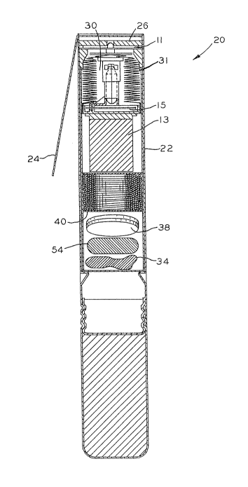
Referring first to Figures 1 and ~, a
sonobuoy 20 prior to deployment has a cylindrically
tubular outer casing 22, wind blade 24 at the outside
upper end thereof and inside thereof in descending
order; parachute 26 having a parachute release mechanism
including the blade 24, and surface unit or floating
portion 30 including the float or bellows 31. Surface
lo unit 30 is connected to upper end of electrically
conductive upper compliance cable 56 the lower end of
which is connected to the upper end of electrically
conductive hard cable 58 the lower end of which is
connected to the upper end of lower compliance cable 36.
Cables 56 and 36 are relatively short and resilient to
reduce vibration shock while cable 58 is longer and is
dimensioned to provide the desired depth of hydrophone
54. The lower end of cable 36 is connected to the top of
sea anchor 38 the lower end of which is connected to
hydrophone 54. In the deployed condition shown in Figure
4, casing 22 and its ballast 32 is free of its previous
contents and sinks to the bottom. An additional ballast
weight 34 which helps in extending the cables is also
sometimes employed. Cables 36, 56 and 58 are initially
contained within a cable pack enclosure 40.
Sonobuoy 20 is dropped or launched from an
aircraft and blade 24 is wind actuated in conventional
manner to deploy parachute 26 having a plurality of
shroud lines connected to the casing 22 by elements
including the release plate 11.
Referring to Figures 2 and 3, after casing 22
enters the water, water floods sea water battery 13 and
the battery 13 provides current to the electronics
components on transmitter circuit board 15 and the other
components as needed. Thus, the salt water provides the
missing electrolyte and thereby actuates the battery. In
particular, a current flows to actuate an explosive
.
PHA 40.588 7 13.2.19gl
squib in a known manner to drive the pin 21 against
compressed gas cartridge 19 puncturing the end of the
cartridge and releasing carbon dioxide or similar gas to
fill the region 23. Note that the compressed gas
cartridge 19 is within the sealed region 23 and no
connection to the now open end of the cartridge 19 is
needed.
Region 23 is a sealed region defined below by
rigid plate 25 having an annular rim 27 which sealingly
receives the lower skirt 29 of bellows 31 and forming
therewith the surface unit 30. Bellows 31 exerts an
increasing upward force on release plate 11 as more gas
is released into region 23 which force eventually causes
plate 11 to buckle or bend at the weakened regions
indicated generally at 33 and 35 and, with additional
bending, the ends of the plate 11 slip free of the
sidewalls of the casing 22 separating the releas~ plate
11 and the attached parachute shroud line retaining cup
18 from the casing. With release plate 11 and retaining
cup 18 gone, the chamber 23 is free to continue
expansion and surface unit 30 is ejected upwardly. A
helper spring may sometimes be employed to aid ejection
of the surface unit upwardly. A pair of flexible antenna
wires 37 and 39 are connected at one end to the
transmitter circuit board 15 and at the sther end to the
upper end of the bellows 31 so that as the chamber
expands, the wires 37 and 39 are straightened out and
extend upwardly from the water surface 46 within the
bellows 31 to provide an antenna for transmission of
buoy information.
The surface uni~ itself is a variable volume
sealed chamber of a generally cylindrical configuration
with the sidewall corrugated or shaped like a bellows as
best seen in Figures 2 and 3, and 5 and 6. The upper
part of the surface unit is formed of a semi-rigid
plastic cup having a corrugated sidewall portion and a
closed end describing one of the cylinder ends. A rigid
2 ~
P}~A 40.588 8 13.2.1991
base member 25 which supports the transmitter circuit
board 15 as well as the compressed gas source 19 has a
rim 27 which is sealed to the cup sidewall portion
~skirt 29) and describes the other of the cylinder ends.
In ~igures 5 and 6, an adjacent pair of
conical sidewall sections such as 41 and 43 are at an
acute angle to one another when the float or bellows is
collapsed as in Figure 5 while they intersect in an
obtuse angle when the float is inflated or expanded as
in Figure 6. If sidewall section 41 is somewhat shorter
than sidewall portion 43, the natural resilience of the
sidewall tends to maintain the collapsed volume
configuration o~ Figure 5 as well as maintaining the
expanded volume configuration of Figure 6. In this case,
the float has two natural stable configurations. On the
other hand, the lengths of adjacent sidewall s~ctions
may be substantially equal as in Figures 2 and ~, and
the strength of plate 22 relied on to maintain the
collapsed configuration until the gas is released~ In
either case, the natural resilience of the sidewall
portions tends to maintain a portion of the expanded
volume configuration. Typically, the sealed region 23
will need to be pressurized above atmospheric pressure
in order to expand the float sufficiently to provide the
required buoyancy. This elevated pressure not only
provides additional insurance against leakage into the
region 23, but also allows for scuttling the huoy when
desired.
Scuttling may rely on the natural resilience
of the sidewall portion which tends to maintain the
chamber at a volume which is intermediate or between the
expanded volume and the collapsed volume. A resistance
wire may be affixed to the blow-molded plastic bellows
and overheated on command or after the expiration of a
predetermined time to heat and melt a hole in the sids
or end of the bellows. When this happens, the air
pressure within the float is reduced to atmospheric
2 ~
PHA 40.58~ 9 13.2.l9gl
pressure and the axial length of the float is reduced to
its intermediate unstressed or natural length. The
corresponding u~stressed volume is inadequate to
displace sufficient seawater to buoy up all the
connected components and the buoy sinks. For example,
the threaded retaining ring 32 atop the bellows 31 may
hold a urethane membrane in place and a resistance wire
may be attached between the ends of the antenna wires 37
and 39. When the wire is heated, the membrane ruptures
and the bellows at least partially collapses. Thus, the
resistance wire provides a way to reduce the pressure
within the chamber so that the natural resilience of the
sidewall portion reduces the chamber volume.
In transitioning from Figure 2 to Figure 3,
the axial length of the float is significantly increased
from Ll to L2 and the sidewall length that had been
consumed in a zig-zag pattern now provides significant
axial extension resulting in greatly increased buoyancy.
The mean diameter D of the float is substantially
unchanged hetween the figures. Thus, for either of the
cylindrical configurations shown, the volume is directly
proportional to the length of the float and may
experience anywhere from double to a five or six-fold
increase upon inflation.
From the foregoing, it is now apparent that a
novel buoy surface unit arrangement has been disclosed
meeting the objects and advantageous features set out
hereinbefore as well as others, and that numerous
modifications as to the precise shapes, configurations
and details may be made by those having ordinary skill
in the art without departing from the spirit of the
invention or the scope thereof as set out by the claims
which follow.