Note : Les descriptions sont présentées dans la langue officielle dans laquelle elles ont été soumises.
' ~ 1
1
INSTANTANEOUS TRIP DEVICE OF A CIRCUIT BREAKER
BACKGROUND OF THE INVENTION
The invention relates to a trip device of a molded case
electrical circuit breaker having per pole a pair of contacts
elastically urged into contact in the closed position of the
circuit breaker and capable of separating due to the action of
electrodynamic repulsion forces when the current flowing through
the contacts exceeds a preset threshold to generate limitation
of said current, said trip device having an overload and/or
short-circuit fault detector which actuates an automatic opening
operating mechanism of the circuit breaker on a fault. ,
A state-~f=the-art trip device (US-A-3,631,369) of the kind
mentioned comprises a movable blade, arranged as a bimetal strip
and subjected to the action of 'the electromagnetic trip device.
An extension of the blade protrudes into the gas outflow duct of
the arc extinguishing chamber. When breaking occurs the gas flow
moves the blade to the tripping position. In most circuit
breakers the gas outflow duct is located away from the trip
device and the previously mentioned device is therefore not
applicable. The blade is subjected to 'the polluting action of
the gases and its correct operation is quickly hindered. Each
pole must be equipped with a trip device of this kind and
selectivity of tripping is not conceivable for the actuator
reacting to the gas flow is integrated in the thermal and
magnetic trip device.
The object of the present invention is to achieve a trip device
providing both limitation and selectivity of tripping by simple,
universal and reliable means.
2
SUMMARY Of THE INVENTION.
The trip device is characterized in that said actuating device
constitutes a leaktight assembly only in communication with the
contact zone, and having a limited actuating travel.
The pressure in the contact zone, notably in the arc
extinguishing chamber, is a direct function of the power of the
arc, and can quickly reach high values, for example from 3 to 10
bars. This overpressure acts on a simple membrane or movable
piston device which actuates the circuit breaker tripping
mechanism. The pressure rise and transmission of this pressure
to the detector take place all the more quickly the higher the
currents are. The device is however not sensitive to weak
currents, and spurious tripping on a simple overload can easily
be avoided by providing a return spring of the piston, or of the
measuring membrane.
The actuator is a leaktight or almost leaktight assembly
constituted by 'the cylinder with the piston or membrane and the
connecting duct between the cylinder a;nd the arc extinguishing
chamber. This duct of small cross-section can be relatively. long
and is easily housed in the case. The movement of the piston
only requires a very small gas flow in the duct and this flow
takes place almost totally before pollution of the gases due to
the action of the arc. The actuator is thus protected from these
polluted gases.
High-speed opening of a limiting circuit breaker is not easily
compatible with selectivity of tripping which requires opening
of the circuit breaker directly upstream from the fault, whereas ,
the other downstream circuit breakers remain closed to ensure
continuity of power supply to the sound part of the mains
system. It has been attempted to achieve selectivity conditions
between two circuit breakers fitted serially, by coordinating
3
their tripping curve, but these conditions are difficult to
maintain for the times involved are extremely short. Saturation
phenomena often mask measurement of the differences of the
currents to be broken, and selectivity is not always achieved.
The present invention is based on the observation that a break
in a limiting circuit breaker always generates a high arc
voltage, and thereby a notable arc energy resulting in a
pressure increase in the breaking zone. This pressure increase
is very high-speed, and selectivity can be achieved by using a
return spring weighted in such a way as to trip at a preset
pressure. Indeed, when two circuit breakers of different ratings
have the same short-circuit current flowing through them, the
pressure in the upstream circuit breaker is much lower than if
it had broken on it.s own and selectivity is- automatically
achieved in a particularly simple manner, for orxly the circuit
breaker having the lower rating trips. This selectivity is
absolutely independent from the overload and/or short-circuit
fault detector, whose design can be adapted to its role of
operating on small currents. The action of the fault detector
can be slightly delayed in order to avoid any interference with
the overpressure actuator, which provides instantaneous
protection as soon as it is required.
According to a development of the invention, each pole of a
multipole circuit breaker comprises an overpressure actuator, so
as to operate as soon as an overpressure occurs in any one of
the poles, and to perform tripping as quickly as possible. The
piston of the overpressure actuator can be common to the
different poles, the latter being connected to the piston by
ducts equipped with an anti-return device. The different arc
extinguishing chambers are preferably connected to a common
manifold with a check valve interposed, this manifold itself
being connected by a duct to the piston or membrane of the
overpressure actuator, which acts on the circuit breaker trip
4
bar. Tripping on a fault can be obtained by a standard thermal
or electromagnetic trip device, or by a solid-state trip device
with a polarized relay. All. these trip devices and actuators act
on the same trip bar which releases the circuit breaker opening
mechanism, in a manner well-known to those specialized in the
art.
The overpressures are high, and the overpressure actuator can
therefore comprise a piston of small surface, in the order of
one sctuare centimeter, and this small size makes it easy to
house in a molded case, possibly of an existing device.
BRIEF DESCRIPTION OF THE DRAWINGS
Other advantages and features will become more clearly apparent.
from the following description of an illustrative embodiment of
the invention, given as a non-restrictive example only and
represented in the accompanying drawings, in which s
Figure 1 is a schematic axial section view of a pole of a
circuit breaker ec~aipped with an overpressure actuator according
to the invention;
Figure 2 is an enlarged scale view of the overpressure actuator
according to figure 1.;
Figure 3 is a schematic view of the overpressure actuator
associated with a three-pole circuit breaker;
Figure 4 is a schematic sectional view of an overpressure
actuator associated with a polarized relay of a solid-state trip
device;
Figure 5 represents the variation curves of the tripping
characteristics.
5
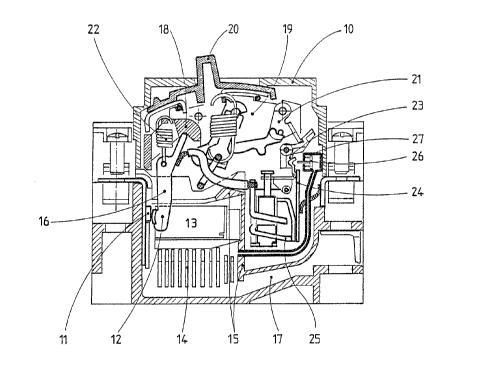
DESCRIPTION OF THE PREFERRED EMBODIMENT
In figure 1, a pole of a molded case circuit breaker 10
comprises a pair of ,contacts 11, 12 located in an arc
extinguishing chamber 13 equipped with deionization plates 14.
The arc extinguishing chamber 13 is bounded by partitions 15 one
of which has passing through it a support arm 16 of the movable
contact 12. The arc extinguishing chamber 13 is almost. leaktight
and communicates by a channel 17 of small cross-section with the
outside of the molded case 10. The movable contact arm 16 is
pivotally mounted on a bar 18 belonging to an operating
mechanism 19, having a manual opening and closing handle 20 of
the contacts 11, 12 and a latch 21 controling tripping of the
mechanism 19. The movable contact 12 is biased by a spring 22 to
the closed position, and is capable of pivoting counterclockwise
due to the electrodynamic repulsion force generated by the
current flowing in the contact arm 16 and contacts 11, 12..The
latch 21 is controled by a trip bar 23 common to the different
poles of the circuit breaker. The circuit breaker comprises a
standard trip device with a bimetal strip 24, and electro-
magnet9.e coil 25, both acting on the trip bar 23. A circuit
breaker of this kind is well-known to those specialized in the
art and does not need to be described in greater detail here. It
is sufficient to recall that when- a short-circuit occurs,
repulsion of the contacts 11, 12 brings about high-speed opening
of these contacts, against the force of the spring 22, this
high-speed opening causing limitation of the short-circuit
current. Opening of the contacts 11. 12 is confirmed by the
operation of the electromagnetic trip device 25 acting via the
trip bar 23 on the latch 21, which opens the circuit breaker
mechanism 19.
According to the present invention, the circuit breaker
comprises an overpressure actuator comprising a piston 26 and
cylinder 27 assembly cooperating with the trip bar 23. Referring
6
more particularly to figure 2, it can be seen that the piston 26
slidingly mounted in the cylinder 27 bears a rod 28 capable of
striking the trip bar 23. A return spring 29.keeps the piston 26
in the retracted position,' represented in figure 2. The face
opposite the rod 28 of the piston 26 is subjected to the
pressure in 'the chamber 30 which communicates via a duct 31 with
the arc extinguishing chamber 13. In the example represented iri
figure 1, the duct 31 opens onto the chamber 13 in the vicinity
of the deionisation plates 14, but pressurization can be
performed at any point of the chamber 13, uniformization of the
pressure inside this chamber being almost instantaneous.
Operation of the circuit breaker according to the invention is
derived from the above description. When the contacts 11, 12
open on a short-circuit, the arc drawn between these contacts
produces heating of the gas contained in the arc extinguishing
chamber 13 and consequently a pressure increase, as a direct
function of the energy of the arc. This pressure increase is
transmitted by the duct 31 to the chamber 30, and as soon as
this overpressure overrides the force of the return spring 29,
causes the piston 26 to slide to the left and actuation of the
trip bar 23 causing the mechanism 19 to open, confirming the
separation of the contacts. Detection of a strong current arc is
extremely fast, whereas the overpressure actuator 26, 27 hardly
operates for a normal break or a weak current, the overpressure
generated in the arc extinguishing chamber 13 being insufficient
to overcome the force of the return spring 29. This same spring
29 enables selectivity to be achieved between two circuit
breakers of different ratings having the same short-circuit
current flowing through them as the pressure developed will be
less great than if it had broken on its own.
The circuit breaker can be multipole and in this case each pole
can be equipped with its own overpressure actuator 26, 27 acting
on the trip bar 23. When a short-circuit occurs, the most loaded
. 7..
pole causes tripping by the pressure increase in its arc
extinguishinc7 chamber 13,,this trip causing all the poles of the
circuit breaker to open.
According to a preferred embodiment, illustrated by figure 3.
three poles P1, P2, P3 of a three-pole circuit breaker
communicate via ducts 31 with a manifold 32, itself connected to
the chamber 30 of the overpressure actuator 26, 27. The orifice
via which the ducts 31 enter the manifold 32 is capable of being
blocked off by a check valve 33, preventing the gases from
flowing from one pole to the other. In the example represented
in figure 3, the pressure increase in the arc extinguishing
chamber of the first pole P1 is the quickest, and this pressure
is 'transmitted via the duct 31 and manifold 32 to the
overpressure actuator 26, 27, the valve 33 being open. The other
two poles P2, P3 are isolated from 'the manifold 32 by closing of
their corresponding valve 33, and the actuating device remains
almost leaktight.
The invention is applicable to circuit breakers with solid-state
trip devices using current transformers to detect an overload or
short-circuit. These current transformers supply a signal to an
electronic processing device which delivers a tripping order to
a polarized relay 34 when preset thresholds are exceeded.
Referring to figure 4, it can be seen that the polarized relay
34 comprises a plunger core 35 held in the retracted position by
a permanent magnet 36, and biased to the operating position of
the trip bar 23, by means of a push-rod 38, by a spring 37. The
tripping ~ order is transmitted to a 'coil 39 which releases the
core 35. The overpressure actuator 26, 27 is adjacent to the
polarized relay 34 and the rod 28 is located facing the trip bar
23 to actuate the latter when an overpressure occurs. The trip
bar 23 bears a lug 40, capable of cooperating with the rear face
of the head of the push-rod 38, leaving a clearance "j",
sufficient for movement of the trip bar 23 due to the action of
8
the overpressure actuator 26, 27, without the core 35 of the
relay 34 moving.~This lug 40 causes discharging of the polarized
relay 34 after the mechanism 19 has tripped.
Operation of the circuit breaker with solid-state trip device is
naturally identical to that described above with a standard trip
device. In both cases, the high-speed operation of the
overpressure actuator allows a small time delay of the trip
device on a fault, this time delay being able to be obtained by
a simple clearance between the electromagnetic trip device and
the trip bar, or between the polarized relay 34 and this trip
bar 23. Any other delay means, for example of the runner type '.
can be used.
The curves in figure 5 show the mode of action of the trip
device according to the invention. Curve "a" shows the
separation distance of the contacts 11, 12, on opening on a
short-circuit by electrodynamic repulsion of the movable contact
12. Curve "b" shows the variation of the arc voltage
corresponding to opening of the contacts 11, 12. Curve "c"
illustrates the increase of the presumed short-circuit current,
whereas curve "d" corresponds to the current limited by the
electrodynamic repulsion of the contacts 11, 12. Curve "e" shows
the pressure variation in the arc extinguishing chamber 13.
Separation of the contacts 11, 12 takes place at a time "tl" and
the overpressure actuator causes opening of the machanism 19,
and thereby that of the three poles of the circuit,breaker at a
time "t2" confirming opening of the contacts by electrodynamic
repulsion. A piston 26, with a diameter of lOmm, has enabled
amply sufficient forces to be obtained to actuate the trip bar
23. A piston of this size can easily be housed i.n the molded
case 10, and the duct 31 of small cross-section enables the
pressure to be picked up at any point of the arc extinguishing
chamber 13. The usual leaktightness of the arc extinguishing
chambers 13 is amply sufficient to obtain the necessary
9
overpressures, and it. is not necessary to provide additional
leaktightness means of these chambers. The assembly is
particularly simple and selectivity is obtained by using return
springs 29 of suitable size.
;.