Note : Les descriptions sont présentées dans la langue officielle dans laquelle elles ont été soumises.
2041~2S
~CKGROUND OF T~E INVENTION
'rhe present invention relates to a golf swing training arld
muscle exercising apparatus which enables a user to simulate the
movements of a proper swing and which also exercises the muscles
of t!~e golfer making such a swing, combined in a slngle
apparatus.
In playing tlle game of golf, optimum shot making performance
is achieved when a golf club is swung on a precise plane using
speciflc muscle groups to maximize the energy transfer from the
club head to a golf ball. In learning to play the game, many
natural tendencies, o~ten learned from playing other sports, must
be overcome to properly position the club head relative to a ball
during a swing. For example, the properly executed swing requires
that the club be swung on an inside to outside path bringing the
lS club head square with respect to tl~e ball at impact using the
large muscles of the body ln combination witll tlle hands to
maximize the pdwer generated during the swing.
Whereas the concepts appear relatively simple, particularly
wllen executed ~y a highly pro~icient golfer, in fact it is often
difficult, lf not imposslble, for a beginner to properly train
himself in the development and execution of a gol~ swing. In thls
regard, many beginning and also experienced players seek the
assistance of teaching professionals to learn the fundamentals
and also to improve a previously developed golf swing. Using thls
teacher method, it is usually possible to provide only visual and
audlble feedback to the player therefore leaving the player to
develop the proper swing movements by himself based on thls
feedback.
_
20~1428
_ Many attem~ts have been made to provide training alld/or
exerclsing devices which enable a golEer to execute a proper golf
swing so that a golEer has physical feedback of the swing motion.
There have also been a number of exerclse devices which are
5 deslgned to stimulate a~d strengthen specific muscle gro--ps
attuned to the swinging of a golf club.
Among the prior art patents relating to such swing training
devices are my own U.S. Patent 3,703,294 for Golf Swing Training
Apparatus. Other prior art patents which are designed to exercise
gol muscles is sllown in U.S. Patents 2,848,234 to Brandon ~or
Golf Swing Conditioner, 3,614,108 to Garten for a Golf Practice
Device, and 4,2229,002 to Masters for a Golf Swing Exercise
Device.
There are a number of prior art devices whlch are
speclfically designed to teach a player t~le proper swing
movements and swing plane positions of a golf club during a golf
swing as shown by the patents to Perrin, 1,893,920 for GolE Swing
Device, 2,328,408 to Beal et al for Golf Stroke Teaching Machine,
2,458,932 to Cottingham for Golf Practicing and Teaching
Appartus, 2,788,214 to Tildon Eor Golf Teaching and Practicing
Device, 3,319,963 to Cockburn for Golf Swing Guiding Device
Including Correct Swing Indicator, 3,429,S71 to Abel for
Programmed Swing Training Device, 3,462,156 to Gentry for Golf
Practice Device, 3,738,661 to Moller for Golf Exercising Device,
4,262,573 to Richards for GolE Swing Simulator Device, 4,580,786
to Shippley for Device For Controlling Golf Swing, and 4,653,757
to Wilkensen for Golf Swing Training Apparatus among a number of
other~, all of which are U.S. Patents.
20~1~28
--3
Whereas the majority of the prior art works quite well Eor
their intended purposes, they are oEten complex in nature
requirlng sophisticated manufacturing and/or installation
procedures. Further shortcolnings, particularly witll the more
5 simple prior art devices, permit the golf club to be swung ln a
number of diE~erent planes while just generally simulating the
~olf swing arc wt~icil actuaLly- can train the golfer to make
improper swing movements. The prior art exercising devices do not
consider the position and plane of the golf club during the
10 exercise device except in a most general way.
~ llen making a golf swing, a line o~ force which moves the
golf club to strike ~he ball starts with the golEer's ~ulling
motion. This pulling motion ~ollows a parabolic arc whicll has a
starting point a~ove and distal to the golEer's right shoulder.
15 'rhls arc needs leverage to gain momelltum and reacll increased
velocity quickly. The human body is deslgned in a way wtlich
predetermines ttle best leverage. The golfer's legs, hips, spine,
shoulders, arms and hands are the levers.
The body's mechanical levers need to be used to put the golf
20 club ~n po~ition at the top of the back-swing in as slmple or
less compllcated means as possible. The swing t-raining machine o~
the present inention has a lever arm that rotates as the golfer
swings, thus the reslstance for the golfer comes Erom behind the
golfer's swing plane; or from pulling. This resistance to the
25 centrifugal force of the swing must come from a moving arm. When
the golfer's leverage is out of alignment with ~he resistance
from the arc arm, the centrifugal force is destroyed and become~
lneffective thus los~ng leverage and causing restraint.
20414~
-
To strike a golE ball, tlle ~orce comes from behind the ball
and goes ~orward with the force of t~le club head at right angles
to tlle target, and a force line directed toward the target will
send the go~f ball straight to the target.
S An improper splnning Eorce rlgl)t to left will cause the ball
to hook. A ball spinning left to right will slice, and a ball
with backspin at 21 revolutions will go straight. The ball may go
higller or lower in trajectory, but not off line.
Now if the resistance is directly back of the arc for a
proper swing, then force applied, but not aligned with tlle
re~istance, will cause swing restraint. Swing restraint may be
used to prevent eitller a slice or hook movement.
The present invention relates to a golf swing trainlng
device which also serves as an exercising device to help a golEer
develop a correct stance and swing as well as to exercise the
mu~cle groups whicll are most effective in transferring maximum
power to a golf ball struck by a swung golf club. The apparatus
lncludes a base, a telescoping support member positioned in a
speciEic angular orientation with respect to tlle base, and a
parabolically shaped rod, one end of which is connected to a
resiliently movable cable and the other end of which is connected
to~a golf grip. The connector attaching the grip to the end of
the rod permits universal movement of the grip with respect to
the rod, which, ln turn, allows the apparatus to be used by a
wlde varlety of golfers having different individual golf swings.
The cable i~ preferably wrapped around a pulley and connected to
a heavy duty spring to provide resistance to the swing motion a3
the device is being used.
--4--
2011428
Further ~eatures include the adjustability of the ~ength of
the cable to increase or decrease the re~lstance of the sprlng
during the performance of a simulated golf swing. ~nother feature
lncludes a telescoping support whicll may be adjustable in a
5 vertical direction to permit use by a variety of golfers of
different heights.
Other features oE the invention include its ability to be
easily assembled and disassembled for transportation and storage.
Still another feature is the provision of a golf ball alignment
device on the support structure which enables a golEer to
determine if he stays in the same position during the execution
of the ~imulated swing.
~ he structure of the support apparatus and the angular
orientation thereof combined with the parabolic rod and the
connection ~etween the grip and the rod provide an apparatus
which permits an easy, smooth Elowing swing to be accomplished
when a proper swing plane is simulated, but which creates
difficulty in the swing when the golEer is out of position. l'he
resistance of the spring connected to the cable also combines
with the aforementioned features to exercise only the proper
muscle groups which produce the most desirable swing movement~ of
a golf swing.
It is therefore an object of the present invention to
provide a new and improved golf swing tralning apparatus and
combined exerclsing apparatus. A further object of the present
invention is to provlde a golf swing training and exercising
apparatus which is simple in construction, easy to use, and i~
20~14~8
`~.
adapted to be Eitted to a variety of different size and difEerent
physLcal chalracteri~tics of golfers, Still another object of tlle
present invention ls to provide a golf swing training and
exercising apparatus in which the apparatus provides Lmmedlate
feedback to the golfer of the execution oE the golf swing.
Other, object~ and advantages of the present invention wlll
become apparent from the following drawings and description.
~041~28
DESCRIPTION OF TE~E DRAWINGS
Figure 1 sl~ows a side elevational view of tlle golf swing
tralning and exercising apparatus.
Figure 2 shows a front elevational view of the apparatus of
5 Figure 1.
Figure 3 shows a top plan view oE the apparatus oE Figure 1.
Figure 4 st~ows a view with a golfer performing a swing
exercise.
20~1428
lUN ~ M~lM~Nl'~
Referring to the drawings, the golE swing training and
exercise apparatu~s 10 of the present invention is formed of a
base plat~orm 12 which supports a vertical mounting Erame 14
S having telescoL)ing upper and lower tubular support elements 16
and 18. 'rhe lower tubular support element 18 is secured to the
base plat~orm 12 by a support plate 20 wl~ich ls attached to tlle
base plat~orm 10 using easily removable fastener members 22 such
a~ wing nuts or the like. ~ pair of support legs 24 provide
a~dltional suUL~ort between tlle base platform 12 and the lower
tul)ular elements 18 of the vertical mounting frame 14.
The upper tubular support element 16 is telescopically
adjus~able within the lower tubular element 18. Pins 26
positioned witll corresponding pin holes (not shown) in eacll o~
the tubular elements 16 and 18 to receive mounting pins 19 to
allow ~or tlle vertical positioning of the elements 16 and 18 with
respect to eacll other to accommodate golfers of various heights.
A thumb screw 28, threadedly attached to tlle lower tubular
element 18, engages tl~e upper tubular element 16 to prevent
movelnent between t11em.
'rhe upper end of the upper tubular element 16 is connected
to a pulley plate 30 which mounts a pulley 32 on one end of a
rotatabLe shaft 34 mounted in an idler bushing 36- secured to the
pulley plate 30. A Elexible cable 38 is wound Oll the pulley 30
and passes over a cable guide 40. The free end o~ the cable 38 is
detachably secured to a heavy duty spring 42 wllicll, in turn, is
connected~to the support plate 20, or any other suitable place on
the ba~e platform 12 or lower portion of the mounting frame 14.
-
20~14~8
-
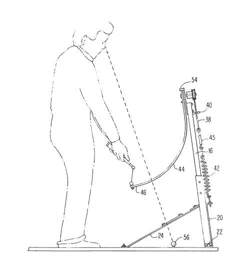
~ parabolic shaped arm 44 is connected to tl~e other end of
the rotata~le shaft 34. rhe parabolic arm 44 is formed with a
radius of approximately 16 inches. The free end 46 oE the arm 44
is connected to a grip rod 4~ preEerably formed with a
5 conventiollal golE grip 50. The grip 50 is attached to the free
end 40 of the arm 44 using a linkage arm 52 which permits
universal movement between the arm 44 and the grip 50 in order to
accommodate the various swing cllaracteristics of the golEers
using tlle apparatus. Irhe pulley plate 30 is provided with an arm
lO stop 54 which maintains the arln 44 in a fixed vertical position
by the action oE the spring 42 pulling against the cable 38. The
cable 38 is provided with a ca~le adjustment means 45 whlch
permits the length oE the cable 38 to be ad justed. It will be
appreclated that the shorter the cable 38 the more the spring 42
15 must be stretched to accommodate the rotation of the arm 44 as
described in detail hereinbelow.
Referring to Figure 1 it can be seen that the vertical
mountlng frame 14 is disposed at an angle of approximately 8 to
lO degrees witll respect to the vertical and tilted ln a
20 direction toward the golfer . Simi] arly the support plate 20 is
secured to the base platEorm 12 at an angle of approximately 20
to 22 degrees with respect to the si~nulate target direction. This
orientation of the apparatus permits a golfer to execute a swing
in a plane whlctl ~or moat golfers is approxlmately 68 degree~
25 from ground level and which allows the arm 44 to rotate on a patll
from the address position above and over the golfer ' s right
shoulder to the proper starting position at the top of the
backswlng .
~0~14~8
In use, a qolfer grips the golf grip 50 and rotates tlle arm
40 in a clockwise directlon until tlle golfer achieves a normal
"address pOSitiOII" relative to a ball 56 which is preferab]y
,permanently attached to the base platform 12. 'rhe arm 44 is lleld
in the address position against the compressive force of the
sprlng 42 or the cable 38 whicn, in turn, impArts a rotational
force on the shaEt 34 uslng the pulley 32. The golfer then makes
a normal backswing while holding the grip 50. At the top of the
backswing, the golEer reverses direction of movements and
commences the downswing against the resistance of the spring 42.
Dependlng upon the strength of the golfer and the adjustment of
tlle lengtll oE the cable 3~, the swing progres~es only a short way
past the normal impact position before tlle spring denies further
movement of the grip 50. ~t t}lis position maximum stress is
lS placed upon tlle muscle groups, particularly in the legs, back and
slloulders, whlcll are used to make the swlng. The golfer may thell
make a number of repetitlon~ of the same swlng motlon not only to
exerclse the various mu3cle groups, but also to provlde muscle
tnemory to the brain as the apparatus is respectlvely swung.
If the golfer's swing motion is not in the proper plane, the
lever arm of tl~e swing training device will encounter resistance
as described hereinabove and the golEer will obtain immediate
feedback that the swing motion is improper. The natural tendency
wlll be for,the golfer to adjust his swing motion to minimlze the
resistance which will result in a proper swing plane.
' Another feature of the apparatus 10 provides a visual
indication that a golfer's head is moving wiht respect to the
ball 56 during a simulated golf swlng by using a sight plate 5
vertically disposed over the ball 56 and mounted on the legs 24.
--10--
20~1~28
~,
The sight plate 5~ is provided with an opening 60 sized to
exactly view the baLl 56. If ttle golfer 1 5 head moves, the ball 56
either partially or completely disappears from the opening 60.
With ttliS feature a user can train himself to stay in
~oqition with respect to the ball to be struck.
It will be appreciated that modlfications may be made to the
above described invention in keeping within the scope of ttle
appended claims.