Note : Les descriptions sont présentées dans la langue officielle dans laquelle elles ont été soumises.
-
204 25 1 ~
TRANSMISSION QUALITY ASSESSMENT ARRANGEMENT
The present invention relates to a transmission
_ quality assessment arrangement for a communication
switching sYstem wherein a stream of cells of information
is transmitted from an inPut to an outPut over a same
communication path.
Such a communication switching system is already
known in the art, e.g. from the EuroPean patent apPlication
No 88900074.1 (M. DE PRYCKER 2-2). Therein a stream of
cells of information belonging to a same communication is
transmitted over a same virtual communication path
established at the start of the communication by means of a
path setuP cell.
To assess the transmission quality of such a
communication it would be Possible to number all the cells
thereof but this would require too much bandwidth due to
cell length increase. Instead, it would also be possible
to insert numbered test cells in the stream, each test cell
being provided for a predetermined number of cells and to
assess the transmission quality by verifying if all the
test eells are received at the output. Such a solution has
the advantage of using only a limited amount of additional
bandwidth but it onlY permits to verify that due to
transmission errors test cells are lost and not that other
cells are lost or that cells are added to the
communication. So the accuracY of the arrangement is
relatively small.
An object of the present invention is to Provide a
*
20~2~ 1 ~
more effective transmission quality assessment arrangement
which while using a limited amount of additional bandwidth
nevertheless allows to assess the transmisslon quallty wlth a
relatively higher accuracy.
According to one aspect of the lnventlon there ls
provided transmission quality assessment arrangement for a
communlcatlon switching system in which a cell stream of
lnformatlon cells ls transmitted from an input to an output
over a common communication path, said arrangement comprising:
an input circuit associated wlth sald input for inserting in
an original cell stream a test cell havlng an assoclated tag
not present in the original cell stream and corresponding to a
flrst count lndlcatlve of an orlglnal cell posltlon at whlch
the test cell was lnserted in the original cell stream to
thereby form a modlfled cell stream whlch ls transmitted over
the common communlcation path; an output clrcult associated
with said output for countlng the cells ln sald modlfled cell
stream to thereby determlne a second count lndlcatlve of the
flnal cell posltlon of sald test cell ln sald modlfled cell
stream after lt has been transmltted over the common
communlcation path and recelved by the output; and a quallty
ascertalnlng clrcuit further comprlslng a comparator for
comparlng said flrst count wlth sald second count and
evaluat lon clrcult ry coupled to sald comparator for derlvlng
from sald comparlson an lndication of the cell transmisslon
quallty.
Accordlng to another aspect, the lnventlon provldes
transmission quality assessment arrangement for a
72430-150
2 04 25 1 ~
communlcatlon swltchlng system ln whlch a cell stream of
lnformation cells is transmitted from an input to an output
over a common communlcatlon path, sald arrangement comprlslng:
an lnput clrcult assoclated wlth sald lnput for lnsertlng ln
an orlginal cell stream a test cell having an associated tag
indicatlve of an orlglnal cell positlon at whlch the test cell
was lnserted ln the orlglnal cell stream to thereby form a
resultant modlfled cell stream before lt ls transmltted over
the common communlcatlon path; an output circuit associated
wlth sald output for measurlng a flnal cell posltlon of sald
test cell ln sald modifled cell stream after lt has been
transmltted over the common communication path and recelved by
sald output, sald output circuit further comprising a cell
counter to count the cells of an output cell stream
corresponding to sald modlfied cell stream and to provide thls
count value on a count output and a test cell analyzer clrcult
to analyze sald test cell from sald modlfled cell stream and
to provlde on an analyzer output the orlglnal cell positlon
lndicating tag thereof; and a quallty ascertainlng clrcuit
further comprising a comparator coupled to sald count output
and to sald analyzer output for comparlng the flnal cell
posltlon of said test cell wlth the orlglnal cell posltlon
lndlcated by sald assoclated tag and evaluatlon clrcultry
coupled to sald comparator for derlvlng from sald comparison
an indlcatlon of the cell transmlsslon quallty, whereln sald
comparator provldes the dlfference of the count value provlded
by sald cell counter and of a second count correspondlng to
sald orlglnal cell posltlon lndlcatlng tag.
- 2a -
72430-150
20425 1 6
,
Slnce the dlfference of the counted cell positlon
and the posltlon lndlcated by the tag indlcates the number of
cells whlch have been lost or added lt ls a good lndlcatlon of
the transmlsslon quallty of the cells.
The above mentloned and other ob~ects and features
of the lnventlon wlll become more apparent and the lnventlon
ltself wlll be best understood by referrlng to the followlng
descrlptlon of an embodlment taken ln con~unctlon wlth the
accompanylng drawlng whlch shows a communlcatlon swltchlng
system 1 to whlch a transmlsslon quallty assessment
arrangement devlce TQA accordlng to the lnventlon ls
assoclated.
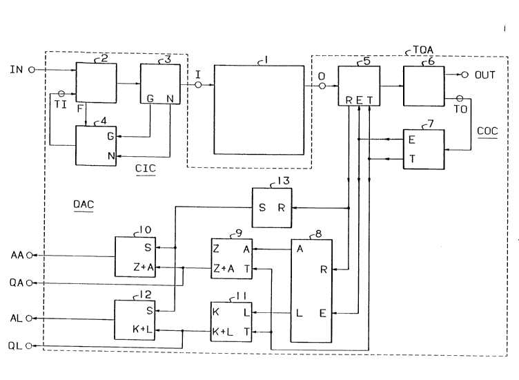
In thls drawlng the connectlons between the blocks
are all represented by slngle wlres although each of them may
be constltuted by a plurallty of such wlres.
The communlcatlon swltchlng system 1 ls for lnstance
- 2b -
72430-150
7 20425 1 6
a digital swiching system of the type disclosed in the
above mentioned European patent application No 88900074.1
In such a switching system cells or Packets of information
belonging to a same communication are transmitted from any
of a plurality of inputs to any of a PluralitY of outputs
along a same virtual transmission path which has been
determined previously bY a path setup cell. Since in the
following description only a single communication on a same
Path will be considered only one input terminal I and one
outPUt terminal 0 of this path in the switching system 1
_ are shown.
-
~ The transmission quality assessment arrangement TQA
includes a cell input circuit CIC couPled to input terminal
I, a cell output circuit COC coupled to output terminal 0
15 and a transmission quality assessment circuit QAC coupled
to the cell output circuit COC.
The cell input circuit CIC comPrises a cell input
and multiplexer circuit 2, a cell inPut counter 3 and a
test cell generator 4. The input multiplexer circuit 2 has
20 a normal cell input IN, a test cell input TI, an enable
outPut F connected to the test cell generator 4 and an
output which is coupled to the input terminal I of the
switching system 1 via the counter 3 having an enable
output G and a count outPut N both coupled to like named
25 inputs of the test cell generator 4. The output thereof is
connected to the test cell input TI of the inPut and
multiplexer circuit 2. The enable output F is activated
when the circuit 2 detects that there is a free cell
position because no normal cell has been received, whilst
30 the enable output G is activated when the counter 3 has
counted a predetermined number of cells, say M.
The cell output circuit COC comprises a cell output
counter 5, a cell outPUt and demultiplexer circuit 6 and a
test cell analyser 7. The output terminal 0 of the
35 switching system 1 is connected, via the cell output
-I ~ 20425 1 6
counter 5. to the inPut of the output and demultiPlexer
circuit 6 having a normal cell output OUT as well as a test
cell output TO which is coupled to the like named input of
the test cell analyzer 7 provided with a trigger output T
and a number output E. The latter outputs are coupled to
like named inputs of the counter 5 and of the test quality
assessment circuit QAC to which also a count output R of
the counter 5 is connected.
The quality assessment circuit QAC comPrises a
comparator 8. an added cells accumulator 9. an added cells
threshold circuit lO. a lost cells accumulator 11, a lost
cells threshold circuit lZ. and a modulo cell counter 13.
The circuits 9. 10. 11, 12 and 13 constitute evaluation
circuitry. The respective outputs R and E of the counter 5
and the test cell analyzer 7 are couPled to inPuts of the
comParator 8. The latter has outPuts A and L which are
coupled to like named increment inputs of the accumulator 9
and 11 respectively. both these accumulators having an
enable input T to which the enable output T of the analyzer
7 is linked. The accumulators 9 and 11 have respective sum
outputs Z + A and K + L which constitute respective output
terminals QA and QL of the TQA and which are moreover
coupled to like named inputs of the threshold circuits 10
and 12. The latter also have a reset input S connected to
an outPUt of the counter 13 whose input R is connected to
the count output R of counter 5. Outputs AA and AL of the
threshold circuits 10 and 12 constitute alarm output
terminals of the TQA.
The above described transmission quality assessment
arrangement TQA operates as follows when normal cells
belonging to a same communication are applied to the input
terminal IN. Each of these cells has a header and a data
field: the header contains information identifying the
communication to which the cell belongs and a tag
indicating that it is a normal cell. whilst the data field
~2~
contains data.
When such a normal cell is applied to the input
terminal IN the cell inPut and multiplexer circuit 2
derives therefrom that a normal cell is concerned and feeds
the latter to the counter 3 which counts the cell and then
applies it to the inPut terminal I of the switching system
1. The counter 3 also provides at its count output N a
number equal to the normal cell count Plus 1 and applies it
to the generator 4. However. this signal has no effect on
the generator 4 as long as the enable inputs G and F
thereof are not simultaneously activated.
In the switching sYstem 1 the cell is transmitted to
the outPut terminal O where it is counted by the counter 5
and then applied to the output terminal OUT via the cell
output and demultiplexer circuit 6 after the latter has
detected from the cell header that a normal cell is
concerned.
To be noted that the cell count provided at the
output R of the counter 5 is applied to both the comParator
8 and the modulo counter 13 of the quality assessment
circuit QAC which will be considered later.
Returning to the cell input circuit CIC, when the
input and multiplexer circuit 2 detects the absence of a
normal input cell and therefore a free cell position it
activates its enable output F. However this has no effect
as long as the counter 3 has not reached the cell count M.
When this happens this counter 3 pro~ides the cell count
M+1 to the generator 4 and as a consequence the latter then
generates a test cell similar to a normal communication
cell i.e. with a header containing information relating to
the communication to which the test cell belongs and an
identification tag indicative of a test cell. and with a
data field storing a position indicating tag constituted
by the abo~e cell count or cell Position M ~ 1. The test
cell thus generated is applied to the test cell input TI of
2~2~ ~
_
the input and multiplexer circuit 2 and is then transmitted
via the counter 3 and the switching system 1 to the counter
5 as the (M + l)th cell of the communication i.e. of the
resultant cell stream of normal and test cells. In the
counter 5, amongst the others, the test cell is counted and
the count value M + 1 is applied to the inputs R of 8 and
13, the test cell being applied to the output and
demultiplexer circuit 6. When the latter finds out that a
test cell is concerned it applies the test cell to the test
cell analyzer 7 via its output T0. The analYzer 7 then
extracts the position indicating tag M ~ 1 from the data
field of the test cell and apPlies it to the count inPuts E
of the cell counter 5 and of the comParator 8. It also
activates its trigger outPut T to indicate that it has
received a test cell. As a consequence of M + 1 being
applied to the input E of the counter 5 the count value
stored therein is changed to M + 1 if it was not Previously
in that condition and in the comparator 8 the value at the
input R is comPared with the value M + 1 at the input E.
Because under normal circumstances both values are equal
the values appearing on the outputs A and L of the
comparator 8 are both equal to 0. Indeed. at the output A
the comparator 8 provides the difference value R-E which is
zero or positive when the cell count R is equal to or
larger than the expected cell count indicated by the number
M + 1 provided on the outPUt E. This happens when
everything is normal or when cells have been added to a
communication respectively. the number of added cells being
equal to R-E. In an analogous way, at its output L the
comparator 8 provides the difference value E-R which i5
zero or Positive when the cell count R is equal to or
smaller than the exPected cell count M + 1 provided at the
output E. This happens when everything is normal or when
cells have been lost from a communication respectively, the
number of lost cells being equal to E-R.
2~51~
Supposing everything i5 normal the values A = 0 and
L = 0 are added to the accumulator values Z and L supposed
to be already stored in the accumulators 9 and 11
respectively. The resultant values Z + A and K + L are
provided at the respective outputs QA and QL when the
enable signal T is activated.
These values aré indicative of the quality of the
transmission since theY indicate the number of added and
lost cells respectively at the moment of arrival of a test
cell.
The values Z + A and K + L are also applied to the
.,
threshold circuits 10 and 12 each of which activates the
signal of its respective alarm outPut AA or AL when the
value Z + A or K + L exceeds a respective threshold value.
However, in order that an alarm signal should only be given
when the ratio of the number of added or lost cells and a
predetermined total number of cell exceeds a predetermined
limit value, each of the threshold circuits is reset when
the modulo counter 13 has counted this Predetermined total
number and has accordingly activated its output S.
When due to a transmission error one or more cells
have been added to a communication, e.g. by transformation
of a cell from another communication, it is clear that the
cell count R provided by the counter 5 when the test cell
with number M + 1 is received will be larger than M + 1,
say M + n, so that the value (M + n)-(M + 1) = n - 1 or A
will aPpear at the output A of the comparator 8 and will be
added in the accumulator 9 to the value Z of PreviouslY
added cel 15 stored therein. When the resultant value Z I A
exceeds the threshold of circuit 10 before it has been
reset by the counter 13 via its outPut S the alarm output
AA will be activated. Necessary measures maY then be taken
to remove the error.
In an analogous way, when due to a transmission
error one or more cells of a communication have been lost
~2516
_
it is likewise clear that the cell count R provided by the
counter 5 when the test cell with number M + 1 is received
will be smaller than M + 1. say M - m. so that the value tM
+ 1) - (M - m) = m + 1 or L will appear at the output L of
the comparator 8 and will be added in the accumulator 12 to
the value K of previously lost cells stored therein. When
the resultant value K + L exceeds the threshold of circuit
12 before it has been reset bY the counter 13 via its
output S the alarm output AL will be activated.
The generator circuit 4 also preferably includes a
timer (not shown) which indePendent 1Y from the condition of
.
~ the inputs G and F generates a test cell each time a
predetermined time interval has elaPsed and aPPlies it to
the multiplexer input TI having priority over the other
input IN thereof. In this way one is sure that a minimum
number of test cells will be transmitted.
While the PrinciPles of the invention have been
described above in connection with specific apparatus, it
is to be clearlY understood that this description is made
onlY by way of examPle and not as a limitation on the scope
of the invention.