Note : Les descriptions sont présentées dans la langue officielle dans laquelle elles ont été soumises.
2 ~
CONTROLLED DEFLECTION ROLL
BACKGROUND OF TlHE INVENTION
1. Field of the Invention
The present invention relates to a new and improved
construction of a controlled deflection rol;L comprising a roll
shell or jacket which is rotatable about a stationary carrier or
support, wherein this roll shell or jacket is supported or braced
against the stationary carrier or support by means of at least
one support or pressure element exerting a pressing force in the
support direction of the support or pressure element.
2. Discussion of the Backqround and Material Information
Such controlled deflection rolls are typically employed
for the pressure or pressing treatment of a web which passes
through a pressure- or roller apparatus and are known, for
instance, from United States Patent No. 3,802,044, granted April
9, 1974, and entitled "CONTROLLED DEFLECTION ROLL".
As described in this patent, the support or pressure
elements can be designed as hydrostatic support or pressure
elements, or else can be constructed in a different fashion, such
as hydrodynamic, pneumatic, magnet.ic or mechanical, for example,
applied by means of spring force, support or pressure elements,
or even as pressure cushions or sealed pressure chambers.
P10075
2~ 7
At times these controlled deflection rolls are equipped
with a so-called cantilever device. With a controlled deflection
roll of the aforementioned type, this canti:Lever dPvice enahlQs
exchange of the roll shell or jacket without the need to
dismantle the controlled deflection roll out of the machine.
Also, in many cases it is necessary to be aLble to exchange the
roll shell or jacket relatively rapidly externally of the
machine, especially in order to maintain within limits the number
of reserve rolls which must be held in readiness at a roller
apparatus or mill.
With prior art rolls it was necessary to expose the
internal parts or components, especially the support elements,
when exchanging the roll shell or jacketO Hence, the pressurized
oil present in the roll, which was released during exchange of
the roll shell or jacket, constituted a disturbance.
Additionally, the mounting of a new roll shell or jacket upon the
support elements of the roll required an undesirable large amount
of time, and a considerable expenditure in personnel and
equipment, particularly, in order to prevent damage to the seals
within the interior of the roll and to accommodate these seals
to the new roll shell or jacket as well as to ensure for a
sufficiently good and functionally reliable mounting of the new
roll shell or jacket upon the support elements.
SUMMARY OF THE INVENTION
Therefore, with the foregoin~ in mind, it is a primary
- 2 - P10075
2 `~
object of the present invention to provide an impro~ed
construction of controlled deflection roll which is not afflicted
with the aforementioned shortcominys and drawbacks of khe prior
art.
Another and more spacific object of the present
invention aims at the provision of an improved construction of
a controlled deflection roll which enables a rapid exchange of
the roll shell or jacket thereof, particularly without requiring
the dismantling of the controlled deflection roll out of the
machine, but also can be undertaken externally of the machine,
with the pressurized fluid medium remaining within the controlled
deflection roll, without impairment of the functionality of seals
and bearings of the controlled deflection roll by virtue of the
exchange of the roll shell or jacket, and with a reduction in the
amount of time and personnel as well as the equipment required
for the roll shell-exchange operation.
Now in order to implement these and still further
objects of the present invention, which will become more readily
apparent as the description proceeds, the controlled deflection
roll of the present development is manifested, among other
things, by the features that the roll shell comprises an outer
roll shell part and an inner roll shell part. In the operating
condition or state of the controlled deflection roll, the outer
roll shell part and the inner roll shell part ~orm a press or
force fit with one another. In order to be able to exchange the
outer roll shell part there can be gen~rated a play between both
- 3 - P~0075
2 ~
the outer roll shell part and the inner roll shell part which is
sufficient to enable an axial movement of the outer roll shell
part in relation to the inner roll shell part. This play allows
removal of the outer roll shell part and the mounting of a new
outer roll shell part of the roll shell.
The press or force fit required to establish a
sufficiently fixed or sturdy interconnection of the inner roll
shell part and the outer roll shell part with one another can be
realized, for example, by exerting a pressing force from the
interior of the controlled deflection roll upon the inner roll
shell part, for instance, by applying an hydraulic force, such
as by means of a hydraulic medium at an excess or overpressure,
or by pneumatic, electro-magnetic or mechanical means, or else,
however, by virtue of the inherent elasticity of the inner roll
shell part or the outer roll shell part~
According to an advantageous construction of the
controlled deflection roll as contemplated by the present
invention, an hydraulic pressure can be built-up by means of the
pressurized fluid medium which is required in any event for the
hydraulic support or pressure elements. This hydraulic pressure
then presses the inner roll shell part against the outer roll
shell part of the roll shell. In order to be able to produce the
necessary excess pressure, the outflow of the pressurized fluid
medium from the support elements can be throttled in a suitable
manner. For the exchange of the outer roll shell part of the
roll shell there is eliminated the throttling of the outflow or
_ ~ _ P:L 075
2 ~
discharge of the pressurized fluid medium, so that there is
formed an adequate play between both of the roll shell parts
which enables removal of the outer roll shell part of the roll
shell.
However, it is also possible to achieve a form locking
or frictional conneckion between both parts of the roll shell in
that there is pre-biased the inner roll shell part, so that this
inner roll shell part, even without the exertion of any forces,
produces a suf~icient press or force fit with the outer roll
shell part of $he roll shell. Then, for the purpose of producing
the play which is needed for the removal or drawing-off of the
outer roll shell part from the inner roll shell part, the
interior of the controlled deflection roll is subjected to a
negative pressure or vacuum until the outer roll shell part of
the roll shell can be easily withdrawn from the inner roll shell
part.
In the aforementioned cases, it is only the outer roll
shell part, which is subjected to wear, which is exchanged or
replaced, whereas the inner roll shell part of the roll shell
remains seated upon the stationary or non-rotatable carrier or
support. The seals and bearings are not affected during mounting
of a new outer roll shell part and the functionality or
operability thereof is fully maintained, that is to say, there
are not required any new adjustments or settings for these seals
and bearings.
- 5 - PlQ075
BRIEF DESCRIPTION OF THE DRAWING
The invention will be better understood and objects
other than those set forth above, will become apparent when
consideration is given to the following detailed description
thereof~ Such description makes reference to the annexed drawing
wherein the single figure shows in longi.tudinal sectional view
a controlled deflection roll constructed according to the present
invention and which may be equipped, for example, with an
hydraulically exerted or applied inner roll shell part or a pre-
biased inner roll shell part.
DETAILED DESCRIPTION OF THE PREFERRED EMBODIMENTS
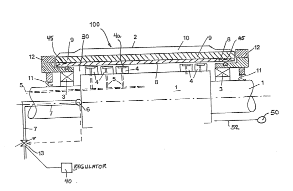
Describing now the drawings, it is to be understoodthat only enough of the construction of the controlled deflection
roll 100 has been depicted therein, in order to simplify the
illustration, as needed for those skilled in the art to readily
understand the underlying principles and concepts of the present
invention.
Turning now to the exemplary embodiments of controlled
deflection roll 100 depicted in the single figure of the drawing,
it will be understood that such controlled deflection roll 100
comprises a non-rotatable or stationary carrier or support 1
about which there is rotatably mounted, by means of suitable
roller bearings 3, a roll shell or jacket 2 as is well known in
this technology. As to the roller bearings 3, such can be
- 6 - P10075
2 ~
constituted by radially fixed bearings, as disclosed, for
instance, in the aforementioned United States Patent No.
3,802,044, or by radially movable bearings which can move at
least in the contemplated support direction, for instance as
disclosed in United State.s Patent No. 3,885,283, granted May 27,
1975, and entitled 'IPRESS ROLL", to which reference may be
readily had, or by using any other suitable known radial guide
structure.
The roll shell or jacket 2 is supported or braced in
10 relation to the stationary carrier or support 1 in the
contemplated support direction by means of support or pressure
elements 4 which can be constructed as hydrostatic support or
pressure elements as disclosed, for example, in the
aforementioned United States Patent No. 3,802,044 or in another
15 known fashion. In this regard, it is remarked there can be al50
used a single continuous support or pressure element or a series
or group of neighboring support or pressure elements extending
in the axial direction of the controlled deflection roll 100, as
likewise known in the art. The hydrostatic support or pressure
20 elements 4 are supplied in known manner, by means of bores or
ducts 5 provided in the stationary carrier or support 1, with a
suitable hydraulic pressurized fluid medium, such as water or
pressurized oil, and pressed against the inside of the roll shell
or jacket 2. The pressurized fluid medium flowing out of the
25 bearing pockets 4a of the hydrostatic support or pressure
elements 4 and into the interior or inner compartment 30 of the
controlled deflection roll 100 is collected by at least one bore
7 - P10075
2~3~
6 of the stationary carrier or support 1 or equivalent structure
and returned to the outside by means of a discharge or outflow
line or conduit 7.
As is known in this tachnology, the hydrostatic or
hydraulic support elements 4 can be grouped toyether into one or
more support zones. Equally possible is the use of a control for
the support elements 4 for altering the effective working width
and the use of counter-effective support or retraction elements
4 which are effective in a direction opposite to the normal
working or effective direction of the support elements 4.
In the illustrated exemplary embodiments, the roll
shell or jacket 2 is composed of at least two roll shell parts,
and specifically, an inner roll shell part 8 and an outer roll
shQll part 9. Depending upon the contemplated use of the
controlled de~lection roll 100, the outer roll shell part 9, in
turn, can be provided with a covering 10 or the like, for
example, formed of an elastic material or rubber. The outer roll
shell part 9 of the roll shell 2 can be highly flexible, or,
however, such can comprise a steel shell or a shell formed in a
different known construction. It is advantageous if this outer
roll shell part 9 possesses a certain stiffness or rigidity in
radial direction. The inner roll shell part 8 is fabricated from
a material which can be expanded or enlarged within certain
limits. This inner roll shell part 8 of the roll shell 2 should
possess a certain flexibility, on the other hand, should have a
certain radial stiffness or rigidity, so that the inner roll
- 8 - P~0075
r~
shell part 8, when expanded, experiences a counter-supporting
action. This property can be attained, for example, by means of
a plastic tube which has been intentionally fabricated to achieve
this purpose, and there can be realized without any difficulty
an elastic elongation in the order of 1%.
The outer diameter of the inner roll shell part 8 and
the inner diameter of the outer roll shell part 9 of the roll
shell 2 are chosen such that without the action of any forces
there exists a play or clearance in the order of tenths of a
millimeter. With the existence of such play or clearance the
outer roll shell part 9 of the roll shell 2 can be easily moved
in axial direction, in other words, such outer roll shell part
9 can be readily withdrawn or dismantled from the remainder of
the controlled deflection roll 100 and mounted or assembled
thereon, as the case may be. During the exchange or replacement
of the outer roll shsll part 9 which has been subjected to wear,
the inner roll shell part 8 remains seated upon the remainder of
the controlled deflection roll 100 and ensures for the
encapsulation of the pressurized fluid medium within the interior
of the controlled deflection roll 100 during the exchange of the
outer roll shell part 9 of the roll shell 2. For the sealing of
the interior of the controlled deflection roll 100 there are
provided at the opposite ends of the controlled deflection roll
100 flexible seals 11 or equivalent sealing structure. The
mount~d outer roll shell part 9 is secured against axial
displacement by a suitable closure or fixation facility provided
at each of the opposite ends of the controlled deflection roll
- 9 - P10075
r~
100 .
During the operation of the controlled deflection roll
100, an excess or overpressure is formed within the interior of
the controlled deflection roll 100. This excess pressure
elastically deforms the inner roll shell parl: 8 of the roll shell
2 and presses such against the outer roll shell part 9. In the
presence of an adequate excess pressure within the interior of
the controlled deflection roll 100, for example, in the order of
1 to 5 bar, the inner roll shell part 8 elastically deforms to
such a degree that this inner roll shell part 8 forms a press or
force fit witll the outer roll shell part 9 and affords a fixed
or sturdy interconnection of these two roll shell parts 8 and 9
with one another and ensures for a positive conjoint rotation of
these two roll shell parts 8 and 9 of the roll shell 2.
In order to ensure for the existence of the requisite
excess pressure internally of the controlled deflection roll 100,
there can be provided, for example, a discharge or outflow valve
13 having a desired throttling action in the discharge line or
conduit 7 for the pressurized fluid medium. This throttle
discharge valve 13 can be manually set, or there can be provided
a suitable regulator or regulation device 40 which controls the
throttle discharge valve 13 as a function of the excess pressure
measured within the controlled deflection roll 100 and can
regulate a predetermined pressure within the interior 30 of the
controlled deflection roll 100. Whereas during the normal
operation of the controlled deflection roll 100 the excess
- 10 - pL0075
. ?,~ ~
pressure within the controlled deflection roll 100 ensures for
the intended function of the controlled deflection roll 100,
following release of the pressure internally of the controlled
deflection roll 100 there is again formed a certain play or
clearance between the outer roll shell part 9 and the .inner roll
shell part 8 of the roll shell 2. As a result, the outer roll
shell part 9 of the roll shell 2 can be exchanged without
difficulty and without the need for any alterations within the
controlled defl~ction roll 100.
According to a further embodiment of the controlled
deflection roll 100, the dimensions, and specifically, the
diameters of the inner roll shell part 8 and the outer roll shell
part 9 are selected such, or the inner roll shell part 8 possess
such a crowning or doming as generally indicated by reference
numeral 45, that upon pressure relief there is already present
a press or ~orce fit. During normal operation of the controlled
deflection roll 100 there is thus not required any excess or over
pressure within the controlled deflection roll 100, and the
discharge of pressurized fluid medium need not be throttled.
Instead, in order to produce the play or clearance between the
inner roll shell part 8 and the outer roll shell part 9 which is
reguired for the replacement or exchange of the outer roll shell
part 9, there is now generated a negative pressure within the
controlled deflection roll 100. This negative pressure can be
produced by connecting a vacuum pump 5~ or the like at a
predetermined line or conduit 52 of the controlled deflection
roll 100. Hence, the inner roll shell part 8 now is retracted
~ P10075
2 ~
or radially inwardly moved by virtue of the pre~sure differential
prevailing within the interior 30 of the controlled deflection
roll 100 and the atmospheric pressure. Consequently, there is
produced the play or clearance required for the dismantling and
mounting, as khe case may be, of the outer roll shell part 9 of
the roll shell 2. Of course, with this embodiment, there are
limited the clamping or engagement forces between the inner roll
shell part 8 and the outer roll shell part 9 of the roll shell
2. However, for many fields of application the prevailing
clamping forces are adequate. However, in this case, the inner
roll shell part 8 must possess a certain radial tension force,
for instance, by providing a certain crowning or doming of the
inner roll shell part 8.
There is also possible a combination of the
aforedescribed two embodiments, that is to say, during operation
of the controlled deflection roll 100 there is generated an
excess pressure within the controlled deflection roll 100,
whereas for the exchange of the outer roll shell part 9 of the
roll shell 2 there is generated a negative pressure within the
controlled deflection roll 100.
- 12 - P10()7.