Note : Les descriptions sont présentées dans la langue officielle dans laquelle elles ont été soumises.
2045840
-- 1 --
FIELD OF THE INVENTION
The present invention relates to equipment for
applying indicia to articles and more particularly to an
apparatus for fastening automatically tags onto timber
with wire staples.
BACKGROUND OF THE INVENTION
To prevent timber from rotting and degrading under
harsh environmental conditions, it is common practice to
pressure treat the wood with chemicals which have the
ability to considerably slow down its natural
decomposition. Such pressure treated timber is normally
guaranteed by the manufacturer for a minimal useful life
and it is common practice to express the warranty
conditions onto a label or a tag fastened on each timber
piece produced by the mill. Presently, tagging the timber
is accomplished manually by using a hand operated stapler
gun for fastening individual tags to timber pieces with
wire staples. Accordingly, this seamingly simple
operation is time consuming, which constitutes a
disadvantage.
2045840
2 --
OBJECT AND STATEHENT OF THE INVENTION
It is an object of the present invention to provide
an apparatus for dispensing and automatically fastening
tags onto timber.
The present invention features an apparatus for
stappling tags onto timber, comprising:
- tag feeder, including:
a) a magazine for holding a continuous strip
comprised of individual tags attached endwise to one
another;
b) a guide system establishing a predetermined
path for advancing the continuous strip away from the
5 magazine;
c) a strip drive engaging the strip for
advancing same along said path;
- a tag applicator station located at an end of said
path, said tag applicator station cutting the tag strip in
individual tags and fastening the tags onto timber with
wire staples, the tag applicator station including:
a) an anvil member;
b) a cutter movable with respect to the anvil
member between operative and inoperative positions, in
the operative position the cutter transversely severing
the strip against the anvil member to separate a tag from
the tag strip;
2045840
-- 3
c) a temporary tag holder adjacent the anvil
member, said temporary tag holder being responsive to
movement of the cutter toward the operative position for
engaging and retaining the tag separated from the tag
strip in a predetermined position;
d) a stapler gun adjacent the temporary tag
holder for applying a staple wire to a timber piece in
registration with the tag applicator station through the
tag separated from the tag strip while it is being held in
the predetermined position in which it extends between the
stapler gun and the timber piece;
- a controller for actuating the strip drive, cutter
and stapler gun in a timed relationship.
In a preferred embodiment, the temporary tag holder
is a leaf spring mounted to the cutter and resiliently
clamping the tag against a stationary abutment plate for
holding the tag in a proper position while a wire staple
is being driven in the piece of timber.
In a preferred embodiment, the tag strip is provided
with registration holes arranged longitudinally thereon
which are engaged by the spokes of a sprocket wheel driven
by a stepper motor, rotating the sprocket wheel in uniform
angular movements to advance the strip stepwise by a
length corresponding to the length of a single tag.
2045840
-
4
In a variant, a bar code applicator is provided inthe tag feeder for imprinting or otherwise applying
information on the tag strip in bar code format.
BRIEF DESCRIPTION OF THE DRAWINGS
- Figure 1 is a perspective view of an apparatus for
stapling tags onto pieces of timber constructed in
accordance with the present invention;
- Figure 2 is an enlarged perspective view of a piece
of timber carrying a tag applied by the apparatus shown in
Figure 1;
- Figure 3 is a perspective view of tags in
continuous strip form for use with the apparatus shown in
Figure 1;
- Figure 4 is a top plan view of the apparatus shown
in Figure 1;
- Figure 5 is an enlarged top plan view of the tag
applicator station of the apparatus shown in Figure 1,
more particularly depicting the tag strip cutter in an
operative position; and
2045840
-
-- 5
- Figure 6 is a view similar to Figure 5 except that
the cutter is shown moving toward the inoperative
position.
DESCRIPTION OF A PREFERRED EMBODIMENT
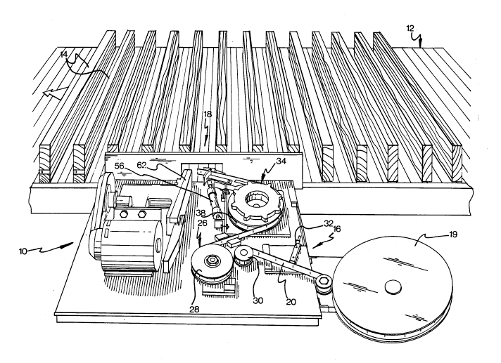
Figure 1 illustrates an apparatus designated
comprehensively by the reference numeral 10 for
automatically stapling tags bearing a certain information
onto pieces of timber. Normally, the machine 10 is
associated with a timber conveying device 12, such as a
conveyor belt on which timber pieces 14 are placed,
oriented transversely to the direction of movement of the
conveyor belt whereby an extremity of each timber piece 14
passes in proximity to the tag applying machine 10 which
dispenses and fastens a tag thereon. In a variant, the
pieces of timber 14 may be held stationary and the machine
10 made moveable to apply a tag to each timber piece.
The tag applying machine 10 has two main components,
namely a tag feeder 16 which supplies tags to an
applicator station 18 whose function is to dispense and
fasten the tags onto the pieces of timber 14 travelling
on the conveyor belt.
2045840
-
6 --
The tag feeder 16 comprises a magazine 19, in theform of a bobbin on which is wound a tag strip 20 whose
structure is best shown in Figure 3. The tag strip 20 is
made of any suitable flexible material such as plastics
material, cardboard or the like and it is comprised of
individual tags 22 which are attached endwise to one
another. In practice, the strip 20 is made from a
continuous band on which is serially imprinted the
information constituting a single tag.
Registration holes 24, longitudinally oriented on the
strip 20, are punched thereon, one per tag.
Referring back to Figure 1, the strip 20 passes from
the magazine 19 through a tensioner assembly 26 comprising
idler pulleys 28 and 30, the pulley 30 being spring biased
to take up the slack in the strip 20 and to build a
certain tension therein. Between the tensioner assembly
26 and the magazine 19 is provided a strip detector 32,
utilizing a photocell for sensing the presence of the
strip 20 and to stop the machine 10 when the supply of the
strip 20 is interrupted which may occur either when the
magazine 19 is empty or when the strip breaks.
25Downstream of the tensioner assembly 26 is mounted a
strip drive 34 which is illustrated in greater detail in
Figures 4, 5 and 6. The strip drive 34 comprises a
2045840 7 _
sprocket wheel 36 with spokes 38 spaced from one another
by a sector length corresponding precisely to the distance
between two adjacent registration holes 24 on the tag
strip 20. Accordingly, when the strip 20 is in a wrapping
engagement with the sprocket wheel 38, a plurality of
registration holes are engaged by spokes 38, preventing
the strip 20 to slip on the sprocket wheel 36.
On top of the sprocket 36 is provided a metallic
starwheel 40 provided with radially outwardly extending
projections 42 corresponding in position to the spokes 38.
Adjacent the sprocket 36 is provided a magnetic pick-
up 44 generating an output signal when one of the
projections 42 passes in proximity thereof. The purpose
of the magnetic pick up 44 is to provide an electric
signal conveying information on the position of the spokes
38 relatively to a fixed point on the frame of the machine
10 .
The sprocket 36 is driven by a stepper mo-tor (not
shown in the drawings) advancing the sprocket wheel in
essentially uniform angular intervals corresponding to the
angular spacing between adjacent spokes 38. In a variant,
a servo-motor may be used which has the advantage of
providing a stepped rotational movement where the length
2045840
of the angular intervals can be controlled by adjusting
the input signal to the servo-motor.
As best shown in Figure 4, the tag applicator station
18 comprises a cutter assembly 46 receiving the strip 20
from the strip drive 34 and cutting the strip 20 in
individual tags. The cutter assembly 46 includes a
stationary anvil plate 48, a blade carrier 50 pivotally
mounted about a vertical axis 52 to the frame of the
machine 10 and a cutting blade 54 mounted to the blade
carrier 50.
As shown in greater detail in Figure 5, the blade
carrier 50 is actuated and pivots about axis 52 in
response to extension and retraction of a pneumatic
piston-cylinder assembly 56.
From the anvil plate 48 projects laterally an
abutment plate 49, which faces a leaf spring 58, mounted
to the blade 54, having a wing 60 which projects away from
the blade 54 to define a narrow angle with the abutment
plate 49. The abutment plate 49 and the leaf spring 58
form a temporary tag holder used to retain a tag severed
by the blade 54 in a predetermined position before the tag
is being fastened to a timber piece 14.
2045840
g
A stapler gun 62 adjacent the wing 60 of the leaf
spring 58 is provided for driving staples into a timber
piece 14 facing the tag applicator station 18. The
stapler gun 62 will not be described in detail because it
is a commercially available item and its construction is
well-known to those skilled in the art. Preferably, the
stapler gun 62 is of the type operating with a continuous
wire supplied from a wire bobbin. In this embodiment, a
magnetic pick-up may be provided (not shown in the
drawings) to sense the presence of the wire. Should the
supply be depleted, the magnetic pick-up causes the
machine 10 to stop. It may also be envisaged to use a
stapler gun operating from a supply of preformed wire
staples, although such an embodiment would require to
1 ~
frequently load the stapler gun with staple cartridges.
The machine 10 operates as follows. The drive system
34 advances the strip 20 by the rotation of the sprocket
wheel 36. As previously mentioned, the sprocket wheel 36
is driven by a stepper motor, and turns in essentially
uniform angular movements selected to provide a sector
length corresponding to the length of a single tag on the
strip 20. As a result, when the sprocket wheel 36
advances by a single step, the tag strip 20 is moved by a
length corresponding to one tag. When the strip has been
advanced to a position where its free extremity extends
beyond the abutment plate 49 as shown in Figure 5, the
~ 2045840
-- 10 --
pneumatic piston-cylinder assembly 56 is extended causing
the blade carrier 50 to pivot about the axis 52 with the
result that the blade 54 engages the anvil plate 48 and
cuts the strip 20 transversely at the boundary between two
adjacent tags. It will be appreciated that the length of
the run of the strip 20 between the sprocket wheel 36 and
the precise location where the blade 54 severs the strip
20 is selected so that the cut is performed exactly at the
boundary between adjacent tags.
When the cutting blade 54 advances toward the anvil
plate 48 for cutting the strip 20, the projecting wing 60
of the leaf spring 58 engages the extremity of the strip
20, pressing same against the abutment plate 49. As a
result, when the strip 20 is severed, the individual tag
which is being cut is held in a generally parallel
relationship with the extremity of the timber piece to
which it is to be applied.
Subsequently, the stapler gun 62 is actuated, driving
a wire staple onto a timber piece 14 facing the stapler
gun, through the extremity of the tag hel-d between the
leaf spring 58 and an abutment plate 49, extending beyond
the abutment plate 49.
~ 2045840
The advancement of the conveyor 12 causes the tag
fastened to the timber piece to be smoothly pulled from
the temporary tag holder formed by the abutment plate 49
and the wing 60.
The cutting assembly 46 is then brought to the
inoperative position by retracting the piston cylinder
assembly 56 which causes the temporary tag holder to open.
The operation of the cutter assembly 46 and the
stapler gun 62 are synchronized whith the drive system 34.
The synchronization signal obtained by the magnetic pick
up 44 provides the information indicating when the
sprocket 36 has completed a step forward, whereby the
precise moment when the cutter assembly 46 and the stapler
gun 62 must be actuated may be precisely determined.
In general, the operation of the machine 10 is
synchronized with the advancement of the timber pieces 14,
so that a tag may be applied at each timber piece
precisely when it passes by the tag applicator station 18.
Various sensor means may be utilized to achieve this
synchronization. For example, photocells or mechanical
switches may be used to sense when a timber piece is to
arrive to the tag applicator 18, commanding advancement of
the drive system 34 and the subsequent actuation of the
cutter assembly 46 and the stapler gun 62.
204584~)
- 12 -
The machine 10 is under the control of an electric
system (not shown in the drawings) receiving signals from
the various signals and outputting command signals to
actuate the various components of the machine 10 in a
timed relationship. Hard wired logic, such as relays and
other electromechanical devices, is preferred because of
its simplicity. The machine 10 may also be placed under
microprocessor control for sophisticated and complex
applications as it will be evident to those skilled in the
art.
In a variant, the machine 10 may be equipped with a
bar code printer (not shown in the drawings) which
typically would be located downstream of the magazine 19
to imprint or otherwise apply on each tag of the tag strip
information in a bar code format. Such printers are known
in the art and they do not require a specific description.
The description of this preferred embodiment should
not be interpreted in any limiting manner as it may be
refined and varied in various ways without departing from
the spirit of the invention. The scope of the invention
is defined in the annexed claims.