Sélection de la langue

Search

Sommaire du brevet 2047013 

Énoncé de désistement de responsabilité concernant l'information provenant de tiers

Une partie des informations de ce site Web a été fournie par des sources externes. Le gouvernement du Canada n'assume aucune responsabilité concernant la précision, l'actualité ou la fiabilité des informations fournies par les sources externes. Les utilisateurs qui désirent employer cette information devraient consulter directement la source des informations. Le contenu fourni par les sources externes n'est pas assujetti aux exigences sur les langues officielles, la protection des renseignements personnels et l'accessibilité.

Disponibilité de l'Abrégé et des Revendications

L'apparition de différences dans le texte et l'image des Revendications et de l'Abrégé dépend du moment auquel le document est publié. Les textes des Revendications et de l'Abrégé sont affichés :

  • lorsque la demande peut être examinée par le public;
  • lorsque le brevet est émis (délivrance).
(12) Brevet: (11) CA 2047013
(54) Titre français: POIGNEE DE CABLE
(54) Titre anglais: CABLE GRIP
Statut: Réputé périmé
Données bibliographiques
Abrégés

Abrégé anglais


A cable grip for improving the performance of cable
bolts for ground support comprises a segmented wedge defining
a cone, each segment having an inside cavity adapted to
conform to a circumference of a cable and serrated grooves
cut into said inside cavity to grip the cable, and a sleeve
consisting of a plastic cone conforming to the conical shape
of the wedge.

Revendications

Note : Les revendications sont présentées dans la langue officielle dans laquelle elles ont été soumises.


1. A cable grip for improving the performance of cable bolts
which are installed in holes drilled in the rock and bounded to the rock with grout
for ground support, comprising:
a) a segmented wedge defining a cone, each segment having an inside
cavity adapted to conform to a circumference of a cable and serrated grooves cut
into said inside cavity to grip the cable; and
b) a sleeve surrounding the cone and consisting of thin plastic material
conforming to the conical shape of the wedge for enalbing the cone to slide within
the sleeve, deform the sleeve and cause the cable grip to wedge into the grout.


2. A cable grip as defined in claim 1 wherein the sleeve
completely covers the segmented wedge to prevent cement intrusion within the
segmented wedge during grouting of the cable bolt.


Description

Note : Les descriptions sont présentées dans la langue officielle dans laquelle elles ont été soumises.

~7~1~


Cable Grip

This invention relates to a cable grip for improving the
performance of cable bolts for ground support.
The use of cable bolts for support in underground mining
is widespread. Steel cables are used to strengthen the rock
mass. They are installed in holes drilled in the rock and
bonded to the rock with grout. However, failure of cable
bolts as support members commonly occurs through failure of
the cable to grout bond. In order to improve the strength of
the cable to grout bond, it has been proposed in Canadian
Patent No. 1,059,351 granted July 31, 1977 to provide
protrusions, such as pressed ferrules, spaced along the
length of the cable. However, such ferrules have to be
preinstalled. Furthermore, they have no post peak strength.
It is the object of the present invention to provide a
cable grip which may be easily installed underground at any
location on a cable.
The cable grip, in accordance with the present
invention, comprises a segmented wedge defining a cone, each
segment of the cone having an inside cavity adapted to
conform to a portion of the circumference of a cable and
serrated grooves cut into such inside cavity to grip the


cable, and a sleeve consisting of a plastic cone conforming
to the conical shape of the wedge.
The sleeve completely covers the segmented wedge to
prevent cement intrusion within the segmented wedge during
grouting of the cable bolt.
The invention will now be disclosed, by way of example,
with reference to the accompanying drawings in which:
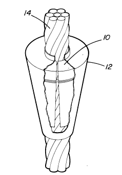
Figure 1 is a perspective view of a cable grip in
accordance with the invention;
Figure la is a section view through the cable grip; and
Figure 2 shows comparative results of tests done on
standard 12" cable bond lengths without grips compared with
the same sample lengths with grips in 3" diameter steel
plpes .
Referring to the drawings, the cable grip comprises two
main components: a segmented wedge 10 and a sleeve 12 which
conforms to the wedge shape. The inside of the wedge fits
around a standard steel cable 14 and has serrated grooves 16
cut into it to grip the cable. The sleeve consists of a
plastic cone, about 1/32" thick which extends past the end of
the wedge to allow adequate sliding of the wedge into the
cone as shown in Figure la. The sleeve is made of plastic
material to allow the wedge to move easily within the sleeve.
By controlling the length of the sleeve it is possible to
control the stiffness of the support for varying ground
conditions. The sleeve also keeps grout away from the wedge-
cable contact. To ensure adequate protection of the grip from

~ ~ f~ 3


cement intrusion, the sleeve extends over the upper edge of
the wedge and contacts the cable at the lower end of the
wedge.
The cable grip, in accordance with the present
invention, relies on the movement of the cable and grip,
relative to the grout, to provide a clamping force to firmly
attach the grip to the cable. To enable the grip to move
relative to the grout, the segmented wedge is installed in a
plastic sleeve. As load is applied to the cable, causing it
to slide within the grout, the segmented wedge is pulled into
its sleeve, wedging into the grout and causing the grip to
tightly clamp the cable. Once the wedge has moved tightly
into its sleeve, it cannot move without crushing grout. The
wedging action of the wedge into its sleeve in the grout
causes the grip to firmly bond to the cable. The wedge/sleeve
assembly prevents failure of the cable to grout bond and
improves the effectiveness of cable bolt support.
Segmented steel wedges from commercially available
barrel and wedges are used as the wedge component of the
cable grip. Zinc aluminum alloys as well as epoxy composites
may also be used as replacements for steel wedges from
commercial barrel and wedges. 1/32" thick Teflon cut from
sheets may be used as the sleeve material.
Laboratory testing has been conducted on the cable grip.
Standard 12" cable lengths, without grips, were tested and
compared with the same sample length with grips. The samples
were cemented in steel pipes. Four series of tests were done

2~'~7~ ~ 3


with water/cement ratios of .35, .40, .50, and .60 after a 7
day cure. The steel pipes used in the test were 12" in length
with an inside diameter of 2.5" and an outside diameter of
2.875". The grips were installed at the centre of the 12"
bond length. The test results are shown in Figure 2. A
typical 12" bond length test with a .40 water/cement ratio,
without a grip, is shown on the graph. The 12" bond length,
with a grip and a .40 water/cement ratio has an over 3 fold
increase in strength compared to standard tests without a
grip. A 12" strength of 12,000 pounds is increased to 38,000
pounds, with a cable grip.
The loading of the cable grip produced a high horizontal
pressure against the wall of the testing pipe which caused
deformation of the pipe wall during the test. In a competent
rock mass the rock would create much higher confinement than
the pipe and the grips would be more effective in increasing
the cable pull out strength.
Although the invention has been disclosed with reference
to a preferred embodiment, it is to be understood that it is
not limited to such embodiment and that other alternatives
are also envisaged within the scope of the following claims.

Dessin représentatif
Une figure unique qui représente un dessin illustrant l'invention.
États administratifs

Pour une meilleure compréhension de l'état de la demande ou brevet qui figure sur cette page, la rubrique Mise en garde , et les descriptions de Brevet , États administratifs , Taxes périodiques et Historique des paiements devraient être consultées.

États administratifs

Titre Date
Date de délivrance prévu 1994-12-13
(22) Dépôt 1991-07-08
Requête d'examen 1992-11-03
(41) Mise à la disponibilité du public 1993-01-09
(45) Délivré 1994-12-13
Réputé périmé 1996-01-08

Historique d'abandonnement

Il n'y a pas d'historique d'abandonnement

Historique des paiements

Type de taxes Anniversaire Échéance Montant payé Date payée
Le dépôt d'une demande de brevet 0,00 $ 1991-07-08
Enregistrement de documents 0,00 $ 1992-01-31
Taxe de maintien en état - Demande - nouvelle loi 2 1993-07-08 100,00 $ 1993-06-28
Taxe de maintien en état - Demande - nouvelle loi 3 1994-07-08 100,00 $ 1994-05-13
Titulaires au dossier

Les titulaires actuels et antérieures au dossier sont affichés en ordre alphabétique.

Titulaires actuels au dossier
NORANDA INC.
Titulaires antérieures au dossier
GENDRON, ALAIN
MILNE, DOUG
Les propriétaires antérieurs qui ne figurent pas dans la liste des « Propriétaires au dossier » apparaîtront dans d'autres documents au dossier.
Documents

Pour visionner les fichiers sélectionnés, entrer le code reCAPTCHA :


Pour visualiser une image, cliquer sur un lien dans la colonne description du document. Pour télécharger l'image (les images), cliquer l'une ou plusieurs cases à cocher dans la première colonne et ensuite cliquer sur le bouton "Télécharger sélection en format PDF (archive Zip)" ou le bouton "Télécharger sélection (en un fichier PDF fusionné)".

Liste des documents de brevet publiés et non publiés sur la BDBC .

Si vous avez des difficultés à accéder au contenu, veuillez communiquer avec le Centre de services à la clientèle au 1-866-997-1936, ou envoyer un courriel au Centre de service à la clientèle de l'OPIC.


Description du
Document 
Date
(yyyy-mm-dd) 
Nombre de pages   Taille de l'image (Ko) 
Page couverture 1994-12-13 1 14
Abrégé 1994-12-13 1 12
Description 1994-12-13 4 138
Revendications 1994-12-13 1 21
Dessins 1994-12-13 1 19
Dessins représentatifs 1999-06-14 1 6
Correspondance de la poursuite 1992-11-03 1 25
Correspondance de la poursuite 1994-01-20 2 41
Demande d'examen 1993-10-15 1 51
Lettre du bureau 1992-11-23 1 40
Correspondance reliée au PCT 1994-09-28 1 40
Taxes 1994-05-13 1 40
Taxes 1993-06-28 1 24