Sélection de la langue

Search

Sommaire du brevet 2047878 

Énoncé de désistement de responsabilité concernant l'information provenant de tiers

Une partie des informations de ce site Web a été fournie par des sources externes. Le gouvernement du Canada n'assume aucune responsabilité concernant la précision, l'actualité ou la fiabilité des informations fournies par les sources externes. Les utilisateurs qui désirent employer cette information devraient consulter directement la source des informations. Le contenu fourni par les sources externes n'est pas assujetti aux exigences sur les langues officielles, la protection des renseignements personnels et l'accessibilité.

Disponibilité de l'Abrégé et des Revendications

L'apparition de différences dans le texte et l'image des Revendications et de l'Abrégé dépend du moment auquel le document est publié. Les textes des Revendications et de l'Abrégé sont affichés :

  • lorsque la demande peut être examinée par le public;
  • lorsque le brevet est émis (délivrance).
(12) Brevet: (11) CA 2047878
(54) Titre français: APPAREIL DE FILTRATION DE L'EAU
(54) Titre anglais: WATER-FILTRATION APPARATUS
Statut: Réputé périmé
Données bibliographiques
(51) Classification internationale des brevets (CIB):
  • B01D 15/08 (2006.01)
  • B01D 27/08 (2006.01)
  • C02F 1/00 (2006.01)
(72) Inventeurs :
  • DEARE, DAVID W. (Etats-Unis d'Amérique)
(73) Titulaires :
  • WILTON INDUSTRIES, INC. (Etats-Unis d'Amérique)
(71) Demandeurs :
(74) Agent: JOHNSON, DOUGLAS S. Q.C.
(74) Co-agent:
(45) Délivré: 1997-11-25
(22) Date de dépôt: 1991-07-25
(41) Mise à la disponibilité du public: 1992-04-13
Requête d'examen: 1993-07-15
Licence disponible: S.O.
(25) Langue des documents déposés: Anglais

Traité de coopération en matière de brevets (PCT): Non

(30) Données de priorité de la demande:
Numéro de la demande Pays / territoire Date
07/596,361 Etats-Unis d'Amérique 1990-10-12

Abrégés

Abrégé français

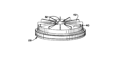
Appareil de filtration pour réduire les contaminants dans l'eau utilisée à des fins domestiques et autres semblables. L'appareil comprend un récipient d'eau avec un réservoir récepteur monté dans le récipient. Le réservoir loge un filtre et un premier passage est formé au sommet du réservoir pour le raccordement du réservoir au filtre. Un deuxième passage permet l'écoulement de l'eau du premier passage pour qu'elle entre en contact avec un écran espacé du premier passage. Une première chambre définie entre le premier passage et l'écran est raccordée par un troisième passage à une deuxième chambre située de l'autre côté de l'écran. Le filtre comprend aussi une paroi de fond définissant des ouvertures qui communiquent avec la deuxième chambre. Le matériau filtrant se trouve entre la première et la deuxième chambre de sorte que l'eau introduite dans le réservoir récepteur descend par le premier passage, passe latéralement par le deuxième passage à la première chambre, remonte en traversant la première chambre et passe ensuite latéralement par le troisième passage pour se rendre à la deuxième chambre. L'eau descend enfin de la deuxième chambre et sort par les ouvertures de la paroi de fond pour entrer dans le récipient d'eau.


Abrégé anglais


A filtration apparatus for reducing contaminants in
water used for household purposes and the like. The apparatus
includes a water container with a receiving reservoir
mounted in the container. The reservoir houses a filter and
a first passage is formed at the top end of the reservoir
for connecting the reservoir with the filter. A second
passage permits the flow of water from the first passage
into contact with a barrier wall spaced away from the first
passage. A first chamber defined between the first passage
and the barrier wall is connected by means of a third
passage to a second chamber located on the other side of the
barrier wall. The filter also includes a bottom wall
defining openings communicating with the second chamber.
Filtering material is located within the first and second
chambers so that water introduced into the receiving
reservoir passes downwardly through the first passage,
transversely through the second passage into the first
chamber, upwardly through the first chamber, and then
transversely through the third passage to the second
chamber. The water then travels downwardly through the
second chamber and outwardly through the bottom wall
openings for entering into the water container.

Revendications

Note : Les revendications sont présentées dans la langue officielle dans laquelle elles ont été soumises.


- 1 -

1. A water contaminant reducing filtration
apparatus for household and like use comprising a water
container, a receiving reservoir mounted in said container,
a filter associated with said reservoir, means forming a
first passage having a top end, said first passage
connecting said reservoir and said filter, a bottom wall for
said filter, said means forming said passage having a bottom
end terminating short of said bottom wall whereby a second
passage is defined between said bottom end and said bottom
wall, a barrier wall spaced from said first passage, a first
chamber defined between said first passage and said barrier
wall, said second passage connecting said first passage and
said first chamber, a top wall defined by said filter, said
barrier wall extending upwardly from said bottom wall, a top
end defined by said barrier wall and terminating short of
said top wall, a third passage defined between said top end
and said top wall, a second chamber located on the side of
said barrier wall opposite said first chamber whereby said
third passage connects said first and second chambers,
openings defined in said bottom wall for communicating said
second chamber with said water container, and filtering
material located in said first and second chambers, water
introduced to said receiving reservoir passing downwardly
through said first passage, transversely through said second
passage into said first chamber, upwardly through said first
chamber, transversely through said third passage, downwardly
through said second chamber, and outwardly through said
openings for entry into said water container.

2. An apparatus according to Claim 1 wherein said
first passage comprises a central passage, said first
chamber comprising an inner chamber surrounding said first
passage, said second chamber comprising an outer chamber

- 2 -

surrounding said first chamber, a side wall for said filter,
said second chamber being defined between said side wall and
said barrier.

3. An apparatus according to Claim 1 wherein said
filter is removably connected to said reservoir.

4. An apparatus according to Claim 3 including
bayonet-type connecting means for said filter.

5. An apparatus according to Claim 2 wherein said
reservoir defines a downwardly-extending stem member, said
stem member forming said central passage, said filter
defining a central section interfitting around said stem
member.

6. An apparatus according to Claim 5 wherein said
central section has a bayonet-type connection with said stem
member.

7. An apparatus according to Claim 1 wherein said
bottom wall is removably attached for facilitating location
of the filtering material within said filter.

8. An apparatus according to Claim 1 wherein the
transverse dimensions of said filter substantially exceed
the vertical dimensions whereby a compact structure is
provided.

9. An apparatus according to Claim 7 wherein said
filter has a diameter between about 4-1/2 and 5-1/2 inches
and a height between about 3/4 and 1-1/2 inches.

- 3 -

10. An apparatus according to Claim 7 wherein the
bottom wall of the filter is substantially flat to thereby
facilitate handling.

11. An apparatus according to Claim 2 wherein said
filtering material comprises a mixture of resin beads and
activated carbon.

12. An apparatus according to Claim 11 including a
fiber filter located at the end of said central passage,
said mixture being located within said inner and outer
chambers.

13. An apparatus according to Claim 12 including
an additional fiber filter positioned between said mixture
and said openings.

14. An apparatus according to Claim 1 wherein said
water container comprises a water pitcher defining an upper
edge, said receiving reservoir including shoulder means
resting on said upper edge for removably holding the
reservoir in position on the pitcher.

Description

Note : Les descriptions sont présentées dans la langue officielle dans laquelle elles ont été soumises.


~7~78


Backqround Of The Invention

This invention relates to a water filtration appa-
ratus which is designed specifically for reducing contami-
nants in water employed for household use or the like.
Although many applications for the apparatus of this
invention will be obvious, the apparatus is particularly
suitable for providing improved drinking water both from the
standpoint of health and safeky and also from the standpoint
of providing more taste-satisfying drinks.

Various attempts have been made to provide means
for achieving removal of contaminants from water. The most
pertinent of such means include the provision of filter
cartridges or the like which are associated with pitchers or
similar water containers. The user will pour the tap water
into a reservoir or other funnel-type structure, and the
cartridge is arranged so that the water must pass through
the cartridqe before entering the pitcher.

Filtering material which may comprise a combination
of a resin and activated carbon is located within the
cartridge so that the water will contact the filtering
material before entering the pitcher. The resin and carbon
media serves to attract various elements typically found in
tap water such as lead and chlorine whereby the water is
cleansed before entering the pitcher.

Examples of prior art structures of the general
type discussed include U.S. Patent No. 8,374 which issued in
1834 as well as subsequently issued Patent Nos. 417,070;
967,905; 2,335,458; 2,376,410 and 4,693,874.

2 0 ~ 7 8 r~ 8


Patent No. 417,070 is of interest in view of the
inclusion of interior barrier walls which direct the flow of
water within a combination reservoir and filter structure.
With this arrangement, the water flowing through the filter
is directed along a sinuous path for purposes of achieving
extended contact between the water and filtering material
while somewhat limiting the size of the filter itself.

Summary Of The Invention

This invention comprises a water contaminant-
reducing filtration apparatus for household use and the
like. The invention comprises a combination of a water
container such as a water pitcher along with a water
receiving reservoir mounted in the container. A filter is
associated with this reservoir so that water poured into the
reservoir will pass through the filter before entering the
water container.

The filter is designed to be removably attached to
the reservoir. Preferably, the filter is attached to a stem
or funnel-shaped member extending downwardly from the reser-
voir with this stem defining a first passage for water
moving through the reservoir. Means in the form of a
bayonet-type connection or the like are utilized for
attaching the filter at the end of this stem.

A second passage is formed at the end of the first
passage, and this second passage is defined between the end
of the stem and the bottom wall of the filter. This second
passage extends into a first chamber defined by the filter
with a barrier wall extending upwardly from the bottom wall
for defining one extreme of the first chamber.

~7~78
~ 3

A second chamber is defined by the filter on the
opposite side of the barrier wall and a third passage is
defined between the upper end of the barrier wall and the
top wall of the filter. This third passage communicates the
first and second chambers. Openings defined in the bottom
wall of the fîlter permit flow of water outwardly from the
filter and into the pitcher or cther water container.

Each of the chambers contain filtering material
which may be of the conventional resin and activated carbon
mix. In the operation of this apparatus, water introduced
into the reservoir flows downwardly through the first
passage and then transversely through the second passage for
entry into the first chamber. By reason of the presence of
the barrier wall, the water flows upwardly through the first
chamber, transversely through the third passage, and then
downwardly through the second chamber before it exits from
the openings defined by the filter bottom wall. By reason
of the location of the filtering material in the first and
second chambers, a cleaner, fresher water is delivered into
the water pitcher.

Brief Descri~tion Of The Drawinqs

Figure 1 is a perspective view of a filter employed
in the apparatus of this invention;
Figure 2 is a bottom plan view of the filter;
Figure 3 is a vertical cross-sectional view of the
filter;
Figure 4 is a vertical cross-sectional view of the
apparatus of the invention comprising a water pitcher and
reservoir with an attached filter; and,
Figure 5 is an enlarged horizontal cross-sectional
view taken about the line 5-5 of Figure 4.

l~n~7~7,~


Detailed Description Of The Preferred Embodiment

The drawings illustrate the combination of the
invention which includes a water container 10 comprising a
water pitcher with a spout 12 and handle 14. A ~onsidera-
tion of the description of the invention will make it clear
that water containers of various other types are suitable
for use in conjunction with the other elements of the
combination.

A watPr reservoir 16 defines a shoulder 18 which
allows for resting of the reservoir on the upper edge 20 of
the pitcher 10. A cover 22 may be employed in association
with this reservoir. It should be understood that the
configuration of the reservoir 16 is dependent upon the
configuration of the pitcher or other water container, and
that various shapes may be assumed by this reservoir.

The reservoir defines a downwardly extending stem
or funnel member 24. As more particularly illustrated in
Figure 5, a plurality of bayonet-type connecting means 26
are formed at the end of this stem. These connecting means
serve as a means for attaching the filter 28 which is
illustrated in detail in Figures 1 through 3.

The filter 28 includes finger-like elements 30
formed for engagement with the connecting means 26 of the
~tem 24. It will be noted in particular that the filter 28
defines a cylindrical section 32 which is adapted to be fit
around the stem 24 with the elements 30 located at a level
above the connecting means 26. Upon rotation of the filter,
the elements 30 are adapted to engage the top of the
connecting means 26 to secure the filter in place.

213~ 7~


The filter includes a bottom wall 34 which is
spaced away from the bottom edge of the cylindrical s~ction
32. Spaced laterally from this cylindrical section is a
barrier wall 36 extending upwardly from the bottom wall 34.
The top edge 38 of this barrier wall terminates short of the
top wall 4Q of the filter. A plurality of radiating fins 42
are shown in association with the top wall; however, these
fins are intended for decorative purposes and may be
eliminated.

A plurality of openings 44 are defined by the
bottom wall of the filter. When considering the over-all
structure, it will be noted that water introduced into the
reservoir 16 will pass through the stem 24. Since the
bottom edge of the stem terminates in spaced relationship
with the bottom wall 34 at about the same point as the
bottom edge of the cylindrical section 32, an annular first
passage is defined for movement of the water laterally
toward the barrier wall 36.

The water then moves upwardly over the top edge of
the barrier wall 36. It will be appreciated that a second
annular passage is formed between this top edge of the top
wall 40 of the filter whereby this upward movement is
followed by transverse movement to the other sid~ of the
barrier wall. The water then progresses downwardly and out
through the openings 44 for entry into the pitcher 10.

The barrier wall 36 serves to form an inner annular
chamber 48 and an outer annular chamber 50. These chambers
are filled with a filtering material 52 which may comprise,
for example, a conventional mix of resin and activated
carbon. Filter pads may be included such as a first filter
pad 54 positioned at the outlet of the reservoir stem, an
before entry into the first chamber 48 and before the water

2nl~ rJ~7~3


overlying pad 56, and a donut shaped pad 58. These pads
thereby provide means for independently filtering water
exits from the openings 44. In a typical application, the
mix of resin and activated carbon particles will be in a
ratio of 2 parts to 1 part. Filter pad material manufac-
tured by Fabricated Filters, Inc., specification number PE
66200, may also be utilized.

It will be appreciated that there has been
described a combination ideally suited for use in the
removal or at least reduction of contaminants such as lead
and chlorine from tap water. The invention may achieve
advantages such as better appearance for the water, better
taste for the water itself and for drinks made ~rom the
water, and a safer drinking water.

Additional significant advantages include the fact
that the filter 28 is very conveniently replaced. Thus, the
reservoir and pitcher are reusable while the filter itself
is intended for replacement periodically, for example, after
about one month of use.

The design of the housing for the filter also
renders it quite compact while still achieving a lengthy
path for contact of the water with the filter matexial.
Thus, the transverse, upward, 'cransverse and then downward
path insures sufficient filtering action even though the
diameter of the filter may be in the order of between about
4-lt2 and 5-1/2 inches and the height may be in the order of
between about 3/4 and 1-1/2 inches.

It will be understood that various changes and
modifications may be made in the above-referenced apparatus
which provide the advantages of the invention without
departing from the spirit thereof, particularly as defined
in the following claims.

Dessin représentatif
Une figure unique qui représente un dessin illustrant l'invention.
États administratifs

Pour une meilleure compréhension de l'état de la demande ou brevet qui figure sur cette page, la rubrique Mise en garde , et les descriptions de Brevet , États administratifs , Taxes périodiques et Historique des paiements devraient être consultées.

États administratifs

Titre Date
Date de délivrance prévu 1997-11-25
(22) Dépôt 1991-07-25
(41) Mise à la disponibilité du public 1992-04-13
Requête d'examen 1993-07-15
(45) Délivré 1997-11-25
Réputé périmé 1999-07-26

Historique d'abandonnement

Il n'y a pas d'historique d'abandonnement

Historique des paiements

Type de taxes Anniversaire Échéance Montant payé Date payée
Le dépôt d'une demande de brevet 0,00 $ 1991-07-25
Enregistrement de documents 0,00 $ 1993-05-11
Taxe de maintien en état - Demande - nouvelle loi 2 1993-07-26 100,00 $ 1993-06-08
Taxe de maintien en état - Demande - nouvelle loi 3 1994-07-25 100,00 $ 1994-06-30
Taxe de maintien en état - Demande - nouvelle loi 4 1995-07-25 100,00 $ 1995-07-05
Taxe de maintien en état - Demande - nouvelle loi 5 1996-07-25 150,00 $ 1996-07-18
Taxe finale 300,00 $ 1997-07-18
Taxe de maintien en état - Demande - nouvelle loi 6 1997-07-25 150,00 $ 1997-07-25
Titulaires au dossier

Les titulaires actuels et antérieures au dossier sont affichés en ordre alphabétique.

Titulaires actuels au dossier
WILTON INDUSTRIES, INC.
Titulaires antérieures au dossier
DEARE, DAVID W.
Les propriétaires antérieurs qui ne figurent pas dans la liste des « Propriétaires au dossier » apparaîtront dans d'autres documents au dossier.
Documents

Pour visionner les fichiers sélectionnés, entrer le code reCAPTCHA :


Pour visualiser une image, cliquer sur un lien dans la colonne description du document. Pour télécharger l'image (les images), cliquer l'une ou plusieurs cases à cocher dans la première colonne et ensuite cliquer sur le bouton "Télécharger sélection en format PDF (archive Zip)" ou le bouton "Télécharger sélection (en un fichier PDF fusionné)".

Liste des documents de brevet publiés et non publiés sur la BDBC .

Si vous avez des difficultés à accéder au contenu, veuillez communiquer avec le Centre de services à la clientèle au 1-866-997-1936, ou envoyer un courriel au Centre de service à la clientèle de l'OPIC.


Description du
Document 
Date
(yyyy-mm-dd) 
Nombre de pages   Taille de l'image (Ko) 
Page couverture 1994-01-29 1 13
Abrégé 1994-01-29 1 35
Revendications 1994-01-29 3 106
Description 1994-01-29 6 253
Dessins 1994-01-29 2 71
Page couverture 1997-11-12 1 64
Dessins représentatifs 1997-11-12 1 7
Taxes 1997-07-25 1 43
Correspondance de la poursuite 1993-07-15 1 40
Lettre du bureau 1992-02-19 1 47
Lettre du bureau 1993-08-18 1 32
Correspondance reliée au PCT 1997-07-18 1 36
Taxes 1996-07-18 1 37
Taxes 1995-07-05 1 32
Taxes 1994-06-30 1 33
Taxes 1993-06-08 1 25