Sélection de la langue

Search

Sommaire du brevet 2051998 

Énoncé de désistement de responsabilité concernant l'information provenant de tiers

Une partie des informations de ce site Web a été fournie par des sources externes. Le gouvernement du Canada n'assume aucune responsabilité concernant la précision, l'actualité ou la fiabilité des informations fournies par les sources externes. Les utilisateurs qui désirent employer cette information devraient consulter directement la source des informations. Le contenu fourni par les sources externes n'est pas assujetti aux exigences sur les langues officielles, la protection des renseignements personnels et l'accessibilité.

Disponibilité de l'Abrégé et des Revendications

L'apparition de différences dans le texte et l'image des Revendications et de l'Abrégé dépend du moment auquel le document est publié. Les textes des Revendications et de l'Abrégé sont affichés :

  • lorsque la demande peut être examinée par le public;
  • lorsque le brevet est émis (délivrance).
(12) Brevet: (11) CA 2051998
(54) Titre français: SYSTEME DE PORTE POUR ABRI
(54) Titre anglais: SHELTER DOOR SYSTEM
Statut: Périmé et au-delà du délai pour l’annulation
Données bibliographiques
Abrégés

Abrégé anglais


ABSTRACT
A shelter door system having two spaced upright posts
forming the sides of a doorframe, a flexible door member
movable vertically between the posts, a roller between the
upper ends of the posts upon which the door member can be
rolled, the roller being supported by frame members, and a
plate structure for supporting each post and securing it to
the shelter, and side panels for covering the openings
between the doorframe and the shelter.

Revendications

Note : Les revendications sont présentées dans la langue officielle dans laquelle elles ont été soumises.


The embodiment of the invention in which an exclusive
property or privilege is claimed is defined as follows:
1) A shelter door system for use in a shelter having
floor tubing, upright tubing and upper tubing forming a
framework over which a flexible cover is draped, the door
system having two spaced upright posts forming the sides of
a door frame, a flexible door member movable vertically
between the posts, the posts each being held in position at
each of their lower ends by a lower plate, each of which is
in the same plane as the floor tubing of the shelter and is
securable to the floor tubing of the shelter by two bars
adjustably secured to the lower plate and diverging away
from it to the floor tubing and being securable thereto, and
at each of their upper ends by an upstanding upper plate,
each of which is securable to a part of the upper tubing
across an opening in the shelter, and a boom supported by
its ends in apertures in the upper plates for accommodating
the door member in a rolled attitude when in its retracted
position.
2) The system of claim 1, wherein each bar has a
small plate secured to its end remote from the lower plate
and each small plate has a pair of holes there through such
that a U-bolt can be placed around the floor tubing and pass
through the pair of holes to securely attach the small plate
to the floor tubing.
3) The system of claim 1, wherein each upper plate
has a bracket secured thereto for securely holding the upper
ends of the posts.
4) The system of claim 1, wherein one of the upper
plates has a larger aperture than a corresponding aperture
in the other upper plate such that an actuator can be fitted
into the larger aperture and the respective end of the boom
can be secured to the actuator.
5) The system of claim 1, including a groove
longitudinally positioned along each post, and a rope
secured to each vertical edge of the door so that the door
can be guided and held in position within the shelter
opening by cooperation between the door edges and the
grooves.
6) The system of claim 5, wherein each groove is
recessed within its post.
7) The system of claim 5 or 6, including a rope means
secured within the edges of the door to provide thickened

edges for passing along the grooves.
8) The system of claim 1, including a triangular
sheet of flexible material securable across the openings
between each post and the shelter.
9) The system of claim 8, wherein each triangular
sheet has a sleeve formed along one edge to accommodate a
rod to secure the sheet beside its respective post, and
eyelets along another side to secure the sheet to a shelter
tubing at the respective side of the shelter opening.
10) A shelter door system kit for use in a shelter
having a tubing framework draped with a flexible cover, the
kit consisting of a boom, a flexible door windable upon the
boom, a pair of posts, a left hand and a right hand frame
member each having; a lower plate and a pair of bars
adjustably securable to the lower plate: and a left hand and
a right hand upper plate each having boom holding apertures
and a clamp to secure the upper end of each post; and clamps
and U-bolts to secure the upper plate and the lower bars to
the tubing framework.
11) The kit of claim 10, including a door actuator.
12) The kit of claim 10 or 11, including a pair of
flexible triangular sheets having eyelets along one side and
a sleeve along another side, and a rod for sliding into the
sleeve for securing purposes.

Description

Note : Les descriptions sont présentées dans la langue officielle dans laquelle elles ont été soumises.

2051 998
This invention relates to a shelter door system which
is capable of being fitted within various sizes and shapes
of door openings. Contrary to fixed shelters which are
constructed as permanent buildinys, temporary shelters come
in various sizes and shapes and are generally constructed of
a frame and covered with a thin flexible sheet material such
as a plastic sheet. Openings within fixed shelters are, by
their nature, of generally standard sizes and doors for such
shelters are available in these standard sizes. However, in
order to be able to install a door system in a temporary
shelter, a means of fitting and properly adjusting the door
to a non-standard sized opening is required. The height as
well as the width of the door system must be adjustable.
This problem is of special concern when the shelter is to be
used, for instance, as a private car garage having a manual
or powered operated door.
The door system of this invention normally uses a
plastic sheet to cover the door opening. This sheet i9 ~ -
attached to a horizontal boom held in position by a vertical
post at each end of the boom. The boom itself can consist
of at least two telescopically joined parts to allow for
adjustment of its length. The two vertical posts are
~ adjustable in length, or can be cut to length, to hold the
- boom at the proper height for the opening. These two posts
can also have tracks with grooves or be shaped with grooves
so as to serve as tracks for the vertical edges of the door
.~ , ' .

:
2051 qq8
sheet.
To ensure proper horizontal spacing for the door sheet
and boom, the posts are held in place by post braces which
are secured to the frame of the shelter and are laterally
adjusted during initial setup. The post braces ensure that
the two posts will remain substantially vertical at all
times and, in particular, under windy conditions.
A preferred embodiment of the invention will now be
described with reference to the attached drawings:
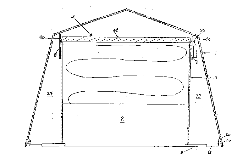
Fig 1 is a representation of the overall door system
with the side panels not shown.
Fig 2 is a representation of the telescopic boom.
Fig 3 is a representation of the upper main frame
member which accommodates the idler side of the boom. ~ : -
Fig 4 is a representation of one of the upper main ~ -
frame members which houses the drive motor of the
boom, and also shows one of the main floor brace~
Fig 5 is a representation of the side panels used to
seal the front portions of the shelter opening which
are at each side of the flexible door member.
Referring to the drawings, Fig 1 ~hows a shelter (1), having
a door opening (2) and a door system (3). Since the size of
the door openings can vary con~iderably, the door sy~tem (3)
is designed to compensate for thsse possib1e variations. To
~ allow for the horizontal variation of the opening, the boom - -
; (42~ can be a piece of cylindrica~ tubing cut to a required
: ~b '
~ . ~
C ~ ''

2051 998
size as shown in Fig 1 and can be as shown Fig 2 wherein it
is a structure having at least two telescopic parts (4) and
(5). These parts can be made of plastic, steel or any other
durable material and can be joined either by means such as a
smaller diameter sleeve (6), as shown, or by having one of
the telescopic parts with a smaller diarneter than the other
part or by other similar means. Along the length of the
boom, the material, such as plastic, tarpaulin or the like,
serving as cover to the opening is attached by means such as
staples, rivets or the like (not shown). Each vertical side
of the door (Fig 1) has a length of rope (not shown)
stitched or otherwise attached into its edge (not shown).
These edges are, in turn, fed into grooved posts (9 of Fig
1) which support the boom. Fig 3 shows the upper main frame
member (8) which ~upports the idler portion of the boom.
The idler portion of the boom (5) is supported in one of
several apertures (7a-7g) in the main frame member (8) so as
to allow compensation for any slope which the ground may
have at that point.
Each of the upper frame members (8) and (11) has a
semi-circular notch (36,37) and a short rod (38,39) made
from steel or other semi-rigid material, welded or similarly
secured close to the notches. The front horizontal tubing
~; (40) of the ahelter fits into the notches of the two upper
main frame members (8) and (11). Each rod (38,39) is then
secured to the tubing (40) by means such as a clamp (not ~-
~:'~: , . . :
3 ~

.
205 1 998
shown). The main frame member (8) is also provided with a
bracket (10). This bracket (10) is firmly attached to the
upper main frame member (8) by means such as welding (not
shown). The bracket (10) ensures that the post (9) will not
sway in the vertical plane as might occur under conditions
of high winds. Each post (9) is made available to suit the
tallest door opening encountered and is then cut to the
proper length to accommodate the particular opening.
Figure 4 shows an upper main frame member (11) having an
aperture (12) which houses a drive motor (35) (Figure 1), or ;~
other suitable actuator, and also shows one of the posts (9)
in place on the upper main frame member (11). The lower
part of each vertical post (9) i9 held in place by mean~
such as a multi-sided metal plate structure having a plate
(13) to which are attached two bars (14) and (15) of
different lengths. These bars are secured in place by means
such as bolts (16) and (17) which allow the bars to be
extended until they come into contact with the floor tubing
(18) of the shelter. The bars are secured to the floor
tubing of the 6helter (18) by means ~uch as small metal
plates (19) and (20). These metal plates are then affixed
100 to the floor tubing by means such as U clamps (21) and (22)
and nuts (23-26). This ensures that the posts (9) will have
the proper horizontal spacing and will be firmly secured to
the shelter ~tructure. Each of areas (27), as shown in
Fig 1, is covered by a means shown as in Fig 5. This figure
~ ,

2051 qq8
shows a section of material (41), roughly triangular, which
has a sleeve (28) sewn to the inner side of the triangular
material (41), next to door post (9), into which a rod (29),
made from steel or other semi-rigid material, can be slid.
This rod (29) is held parallel to post (9) and secured to
110 same by means such as clips (30) at the top of the post and
at its base by means such as a hole (31) drilled into the
multi-sided metal plate 113) shown at Fig 4. The outer side
(furthest from the door post) of the triangular material has ` ::
eyelets (32) spaced therealong preferably at approximately
every 10 centimetres. This allows it to be secured to the
shelter vertical tubing (33) by means such as rope (34)
which is fed through the eyelets (32) and around the shelter
vertical tubing (33).
-" '-
,'.-: ',
' ~
-'' :,.,
~ ' ,"~ ''
-: : :
~; : . -.
~ '~ ~ .''.'';"' ' -

Dessin représentatif
Une figure unique qui représente un dessin illustrant l'invention.
États administratifs

2024-08-01 : Dans le cadre de la transition vers les Brevets de nouvelle génération (BNG), la base de données sur les brevets canadiens (BDBC) contient désormais un Historique d'événement plus détaillé, qui reproduit le Journal des événements de notre nouvelle solution interne.

Veuillez noter que les événements débutant par « Inactive : » se réfèrent à des événements qui ne sont plus utilisés dans notre nouvelle solution interne.

Pour une meilleure compréhension de l'état de la demande ou brevet qui figure sur cette page, la rubrique Mise en garde , et les descriptions de Brevet , Historique d'événement , Taxes périodiques et Historique des paiements devraient être consultées.

Historique d'événement

Description Date
Inactive : Renversement de l'état périmé 2012-12-02
Le délai pour l'annulation est expiré 2011-09-20
Lettre envoyée 2010-09-20
Inactive : CIB de MCD 2006-03-11
Exigences pour le changement d'adresse - jugé conforme 2004-10-06
Inactive : Lettre officielle 2004-10-06
Inactive : Lettre officielle 2001-10-10
Exigences pour le changement d'adresse - jugé conforme 2000-09-20
Inactive : Lettre officielle 2000-09-20
Accordé par délivrance 1994-04-05
Demande publiée (accessible au public) 1993-03-21
Exigences pour une requête d'examen - jugée conforme 1992-05-26
Toutes les exigences pour l'examen - jugée conforme 1992-05-26
Déclaration du statut de petite entité jugée conforme 1991-09-20

Historique d'abandonnement

Il n'y a pas d'historique d'abandonnement

Historique des taxes

Type de taxes Anniversaire Échéance Date payée
TM (brevet, 6e anniv.) - petite 1997-09-22 1997-07-14
TM (brevet, 7e anniv.) - petite 1998-09-21 1998-09-14
TM (brevet, 8e anniv.) - petite 1999-09-20 1999-09-10
TM (brevet, 9e anniv.) - petite 2000-09-20 2000-09-12
TM (brevet, 10e anniv.) - petite 2001-09-20 2001-09-14
TM (brevet, 11e anniv.) - petite 2002-09-20 2002-09-11
TM (brevet, 12e anniv.) - petite 2003-09-22 2003-09-11
TM (brevet, 13e anniv.) - petite 2004-09-20 2004-09-20
TM (brevet, 14e anniv.) - petite 2005-09-20 2005-09-20
TM (brevet, 15e anniv.) - petite 2006-09-20 2006-09-14
TM (brevet, 16e anniv.) - petite 2007-09-20 2007-09-20
TM (brevet, 17e anniv.) - petite 2008-09-22 2008-09-19
TM (brevet, 18e anniv.) - petite 2009-09-21 2009-09-21
Titulaires au dossier

Les titulaires actuels et antérieures au dossier sont affichés en ordre alphabétique.

Titulaires actuels au dossier
RHEAL XAVIER JOSEPH HAMELIN
Titulaires antérieures au dossier
S.O.
Les propriétaires antérieurs qui ne figurent pas dans la liste des « Propriétaires au dossier » apparaîtront dans d'autres documents au dossier.
Documents

Pour visionner les fichiers sélectionnés, entrer le code reCAPTCHA :


Pour visualiser une image, cliquer sur un lien dans la colonne description du document (Temporairement non-disponible). Pour télécharger l'image (les images), cliquer l'une ou plusieurs cases à cocher dans la première colonne et ensuite cliquer sur le bouton "Télécharger sélection en format PDF (archive Zip)" ou le bouton "Télécharger sélection (en un fichier PDF fusionné)".

Liste des documents de brevet publiés et non publiés sur la BDBC .

Si vous avez des difficultés à accéder au contenu, veuillez communiquer avec le Centre de services à la clientèle au 1-866-997-1936, ou envoyer un courriel au Centre de service à la clientèle de l'OPIC.

({010=Tous les documents, 020=Au moment du dépôt, 030=Au moment de la mise à la disponibilité du public, 040=À la délivrance, 050=Examen, 060=Correspondance reçue, 070=Divers, 080=Correspondance envoyée, 090=Paiement})


Description du
Document 
Date
(aaaa-mm-jj) 
Nombre de pages   Taille de l'image (Ko) 
Abrégé 1994-07-08 1 83
Revendications 1994-07-08 2 128
Dessins 1994-07-08 5 266
Description 1994-07-08 5 279
Dessin représentatif 1998-10-27 1 24
Avis de rappel: Taxes de maintien 1997-06-21 1 124
Avis de rappel: Taxes de maintien 1998-06-24 1 119
Avis de rappel: Taxes de maintien 1999-06-21 1 120
Avis de rappel: Taxes de maintien 2000-06-20 1 118
Avis de rappel: Taxes de maintien 2001-06-20 1 120
Avis de rappel: Taxes de maintien 2002-06-24 1 130
Avis de rappel: Taxes de maintien 2003-06-22 1 115
Avis de rappel: Taxes de maintien 2004-06-21 1 118
Avis de rappel: Taxes de maintien 2005-06-20 1 117
Avis de rappel: Taxes de maintien 2006-06-20 1 118
Avis de rappel: Taxes de maintien 2007-06-20 1 121
Avis de rappel: Taxes de maintien 2008-06-22 1 122
Avis de rappel: Taxes de maintien 2009-06-22 1 119
Avis de rappel: Taxes de maintien 2010-06-21 1 122
Avis concernant la taxe de maintien 2010-10-31 1 171
Deuxième avis de rappel: taxes de maintien 2011-03-21 1 128
Taxes 2003-09-10 1 55
Taxes 2001-09-13 1 19
Correspondance 2001-09-13 2 31
Taxes 2002-09-10 2 87
Taxes 1999-09-09 1 29
Taxes 2000-09-11 3 120
Taxes 2004-09-19 3 150
Correspondance 2004-09-19 3 150
Correspondance 2004-10-05 1 13
Taxes 2005-09-19 3 155
Taxes 2006-09-13 1 97
Taxes 2007-09-19 1 82
Taxes 2008-09-18 2 244
Taxes 2009-09-20 1 131
Taxes 1998-09-13 2 98
Taxes 1997-07-13 4 219
Taxes 1996-07-30 3 103
Taxes 1995-07-26 3 98
Taxes 1994-09-01 1 33
Taxes 1993-11-03 1 25
Courtoisie - Lettre du bureau 1992-06-10 1 48
Correspondance de la poursuite 1993-10-12 2 96
Demande de l'examinateur 1992-07-07 2 111
Demande de l'examinateur 1993-05-20 2 102
Correspondance de la poursuite 1993-01-14 3 133
Correspondance de la poursuite 1993-03-21 1 29
Courtoisie - Lettre du bureau 1993-02-14 1 46
Courtoisie - Lettre du bureau 1993-12-14 1 24
Correspondance de la poursuite 1992-05-25 2 72
Correspondance de la poursuite 1993-07-25 1 54
Correspondance de la poursuite 1992-09-07 4 106
Demande de l'examinateur 1992-10-21 2 78
Correspondance de la poursuite 1993-11-30 4 148
Correspondance de la poursuite 1994-01-13 1 28
Correspondance de la poursuite 1993-10-24 1 27
Demande de l'examinateur 1993-09-02 2 80