Note : Les descriptions sont présentées dans la langue officielle dans laquelle elles ont été soumises.
~OMPACT HOT MELT APPLICATO~ 0~0 1~
Background of the Invention
1. Field of the Invention
This invention relates to a hot melt
applicator that stores multiple blocks of solid adhesive
to be dispensed.
2. Description of the Related Art
Many types of hot melt applicators are
adapted for hand-held use so that the molten adhesive can
be conveniently maneuvered and placed at a selected
location on a workpiece. Conventionally, smaller
hand-held hot melt applicators have a manually operated
feeding mechanism for pushing a block of solid hot melt
material toward a melting chamber. Some of the larger
hot melt applicators have an air-operated piston and
cylinder assembly for pushing the blocks of hot melt
material toward the melting chamber with less operator
effort. An improved manually operated feeding mechanism
for a hot melt applicator is described in U.S. Patent No.
4,951,846. U.S. Patent No. 4,457,457 shows a larger
applicator having an air-operated piston and cylinder
feeding mechanism.
Some hot melt applicators are provided with
a storage receptacle for holding extra blocks of solid
hot melt material, so that there is less interruption of
the work operation after the first block of material is
melted and dispensed. The applicator described in U.S.
Patent No. 4,457,457 has a storage receptacle that is
located between and above the melting chamber and the
cylinder of the piston and cylinder assembly. As the
piston of the applicator in U.S. Patent No. 4,457,457 is
retracted, the next block of solid hot melt material
--1--
2 ~
descends through a bottom opening of the receptacle to a
position in front of the piston, whereupon the piston can
be advanced to push the descended block toward the
melting chamber. The piston during advancement also
blocks the bottom opening of the receptacle so that the
remaining blocks of material in the receptacle are
retained in the latter until such time as the piston has
completed its advancement and is then withdrawn to its
starting position to allow the next block to descend
through the opening.
However, there is a continuing desire to
reduce the overall size of hot melt applicators as much
as feasible in order to improve the maneuverability of
the applicator as well as the operator's vision of the
work operation, especially in instances where the molten
adhesive must be placed at a precise location on the
workpiece. While the applicator shown in U.S. Patent No.
4,457,457 has provided satisfactory performance, the
piston and cylinder assembly extends behind the storage
receptacle a significant distance which is somewhat
greater than the length of the blocks to be dispensed,
and additional space is also consumed by the pressurized
air connection at the rearmost end of the cylinder. The
piston and cylinder assembly may also inhibit rearward
movement of the block as the front portion of the block
expands in the melting chamber after a dispensing
operation, possibly causing unwanted molten adhesive to
drip from the applicator's nozzle.
Summary of the Invention
The present invention concerns an
applicator for dispensing molten material from elongated
blocks of solid material, and comprises a frame along
with a melting chamber that is connected to the frame and
that is adapted to rece.ive and melt an elongated block of
s~lid material. The applicator includes a receptacle for
storing at least one elongated block of solid material,
and the receptacle includes a lower opening. A feeding
-2-
........... . . . . . .
'. i
2 0 ~
mechanism is connected to the frame for advancing a block
of solid material from a position beneath the opening and
along a path toward the melting chamber. The applicator
also includes an element movable along the opening from a
first position enabling a block of material to pass
through the opening and toward a second position for
preventing a block of solid material in the receptacle
from passing through the opening. The element is
flexible and movable along a non-straight path when
moving from the first position to the second position. As
such, reduction in the size of the applicator
is facilitated.
Brief Descri~tion of the Drawinas
Fig. l is a side elevational view of the
applicator of the present invention;
Fig. 2 is a rear elevational view of the
applicator shown in Fig. l;
Fig. 3 is an enlarged cross-sectional view
of the applicator taken along lines 3-3 of Fig. 1;
Fig. 4 is an enlarged side view in partial
section of the applicator shown in Fig. 1 along with
blocks of solid material, wherein an arm of the-
applicator has been advanced to push one of the blocks
toward a melting chamber while a flexible element
connected to the arm retains additional blocks in an
overlying storage receptacle; and
Fig. 5 is a fragmentary view somewhat
similar to Fig. 4 except that the arm and element have
been retracted to allow the next block of solid material
in the receptacle to descend to a position in front of
the arm.
Detailed Description of the Preferred Embodiment
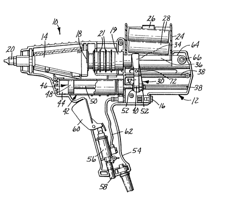
An applicator lO for dispensing molten
material such as hot melt adhesive is shown in Figs. 1-5
and includes a frame 12 that is in the nature of a two
-3-
205~0~
piece, molded housing. A melting chamber 14 (see Fig. 4)
includes a pair of internal electrical resistance heating
elements that are activated by a switch 16. An entrance
18 leads to a somewhat conical cavity in the melting
chamber 14, and molten adhesive exits the melting chamber
14 through a nozzle 20 for application to the work site.
A sleeve 19 is supported by the frame 12
immediately behind the entrance 18 to the melting chamber
14, and functions to align the adhesive block during its
travel through the entrance 18 and into the melting
chamber 14. The sleeve 19 carries a number of spaced
apart, ring-shaped cooling flanges 21 to substantially
prevent melting of portions of the adhesive block that
are adjacent the entrance 18 but outside of the melting
chamber 14.
The frame 12 has a pair of oppositely
extending tabs 22, one of which is shown in Fig. 1. The
tabs 22 are received in square apertures formed in lower
wall portions of a rectangular, box-like storage
receptacle 24. The receptacle 24 may be detached from
the frame 12 for access to areas below when the lower
wall portions of the receptacle 24 ~re flexed outwardly a
sufficient distance to allow the apertures to clear the
tabs 22.
The top of the receptacle 24 has a pair of
curved, inwardly extending fingers 26 (see, e.g., Fig.
2). The receptacle 24 is integrally molded of a plastic
material having sufficient flexibility to enable the
fingers 26 to deflect outwardly and away from each other
when a cylindrical block 28 of solid thermoplastic
material such as hot melt adhesive (see Figs. 4-5) is
pushed through the open top of the receptacle 24.
The applicator 10 also includes a feeding
mechanism broadly designated 30 that is connected to the
frame 12 for advancing the block 28 toward the melting
chamber 14. The feeding mechanism 30 includes an upright
arm 32 that is reciprocally movable in a horizontal
direction viewing Figs. 1, 4 and 5. The arm 32 has a
disk-like head 34 located beneath the receptacle 24 for
20~a.Q~
advancing the block 28 that has descended through a lower
opening 36 of the receptacle 24. The head 34 pushes the
block 28 from a position beneath the opening 36 and along
a path toward the melting chamber 14. A front face of
the head 34 is inclined in a downward and rearward
direction in order to facilitate horizontal movement of
the block 28 toward the melting chamber 14 even in
instances where cantilever forces tend to pivot the arm
32 counterclockwise (viewing Figs. 4-5) as the arm 32 is
advanced by the piston rod 50.
Opposite sides of the frame 12 each include
a pair of parallel channels 38 that are shown in Figs.
3-5. The lower portion of the arm 32 includes two pairs
of opposed, outwardly extending guides 40 which each
slide in a respective one of the channels 38 as the head
34 moves either toward or away from the melting chamber
14.
The feeding mechanism 30 includes an
air-powered piston and cylinder assembly 42 having a
cylinder 44 that is fixed to the frame 12 in a position
directly underlying the melting chamber 14 and the sleeve
19. A piston 46 of the assembly 42 includes a piston
head 48 that is reciprocal within the cylinder 44, along
with a piston rod 50 that extends in a rearward direction
and has an outer end that passes through a hole formed in
a lower portion of the arm 32. A lock ring and washer
assembly 52 is coupled to the rod 50 on each side of the
arm 32 to secure the arm 32 to the piston 46 for
simultaneous movement.
A handle 54 of the frame 12 carries an air
valve 56 coupled by tubing 58 to a source of pressurized
air (not shown). A lever 60 is pivotally connected to
the handle 54 and, when depressed, opens the air valve 56
to communicate the tubing 58 with a length of tubing 62
that extends between the air valve 56 and the rear end of
the cylinder 44 in order to admit pressurized air into
the latter. As the cylinder 44 is pressurized, the
piston head 48 moves to the left (viewing Fig. 4),
thereby retracting the rod 50 and simultaneously moving
--5--
20~0~3
the arm 32 to the left such that the head 34 of the arm
32 moves the block 28 along a path toward the melting
chamber 14.
Referring now to Figs. 4 and 5, the
applicator 10 includes a flat, constant force coil spring
element 64 having one end portion that is loosely wrapped
around a post 66 of the frame 12. The opposite end
portion of the spring element 64 has a hole, and a headed
pin 68 (see Fig. 5) passes through the hole to secure the
element 64 to the top of the head 34 of the arm 32~ By
comparing Figs. 4 and 5, it can be observed that as the
arm 32 moves to the left during pressurization of the
cylinder 44 in order to push the block 28 toward the
melting chamber 14, the spring element 64 unwraps and is
therefor movable along a curved, non-straight path from a
first or coiled position as shown in Fig. 5 to a second
or partially unwrapped position as shown in Fig. 4. As
the element 64 unwinds and approaches the second
position, the uncoiled portion of the spring element 64
supports the blocks 28 remaining in the receptacle 24 to
prevent such blocks 28 from descending by gravity through
the lower opening 36 of the receptacle 24.
Once the arm 32 has approached its limit of
forward movement and the trailing end of the block 28
pushed by the arm 32 is forward of the receptacle 24,
retraction of the arm 32 and spring element 64 to their
respective positions shown in Fig. 5 enables the next
block 28 in the receptacle 24 to drop through the opening
36 into a position in front of the head 34 aligned with
the central axis of the melting chamber 14. The
operation is then repeated by depressing the lever 60 to
pressurize the cylinder 44 in order to again advance the
arm 32 and block 28, while the spring element 64 again
unwraps to support any blocks 28 remaining in the
receptacle 24.
A pair of opposed grips 70 (Figs. 1-3) are
secured to a bar 72 (Fig. 3) that extends through the arm
32, for enabling the operator to retract the arm 32 to
its position shown in Fig. 5 when desired and allow
--6--
,
20~4~Q
another block 28 to descend through the opening 36. The
spring element 64, comprising a resilient metal flat coil
spring, is inherently biased in a manner to urge the arm
32 away from the melting chamber 14. The bias of the
spring element 64 is not sufficient to pull the arm 32
along with the piston rod 50 back to their respective
positions shown in Fig. 5 when the operator releases the
lever 60 to relieve pressure of air in the cylinder 44,
so that the arm 32 need not travel great distances before
again contacting the block 28 and applying pressure to
the same for advancement during the next dispensing
operation. However, the bias of the spring element 64 is
sufficient to just slightly move the arm 32 to the right
viewing Figs. 4 and 5, thereby relieving the pressure of
the arm 32 on the block 28 in order to help avoid
drippage of molten material from the nozzle 20. The
latter feature is especially desirable because material
remaining in the melting chamber 14 after a dispensing
operation may continue to expand and otherwise cause
unwanted molten material to drip from the nozzle 20.
As can be appreciated, the use of a
flexible element such as element 64 is advantageous in
that little space behind the receptacle 24 is needed, and
thus the reduction in overall length of the applicator is
facilitated. The piston and cylinder assembly 42, being
conveniently located below the melting chamber 14 and the
sleeve 19, are normally out of the operator's line of
sight to the workpiece. As such, the applicator 10 is
both maneuverable and compact.